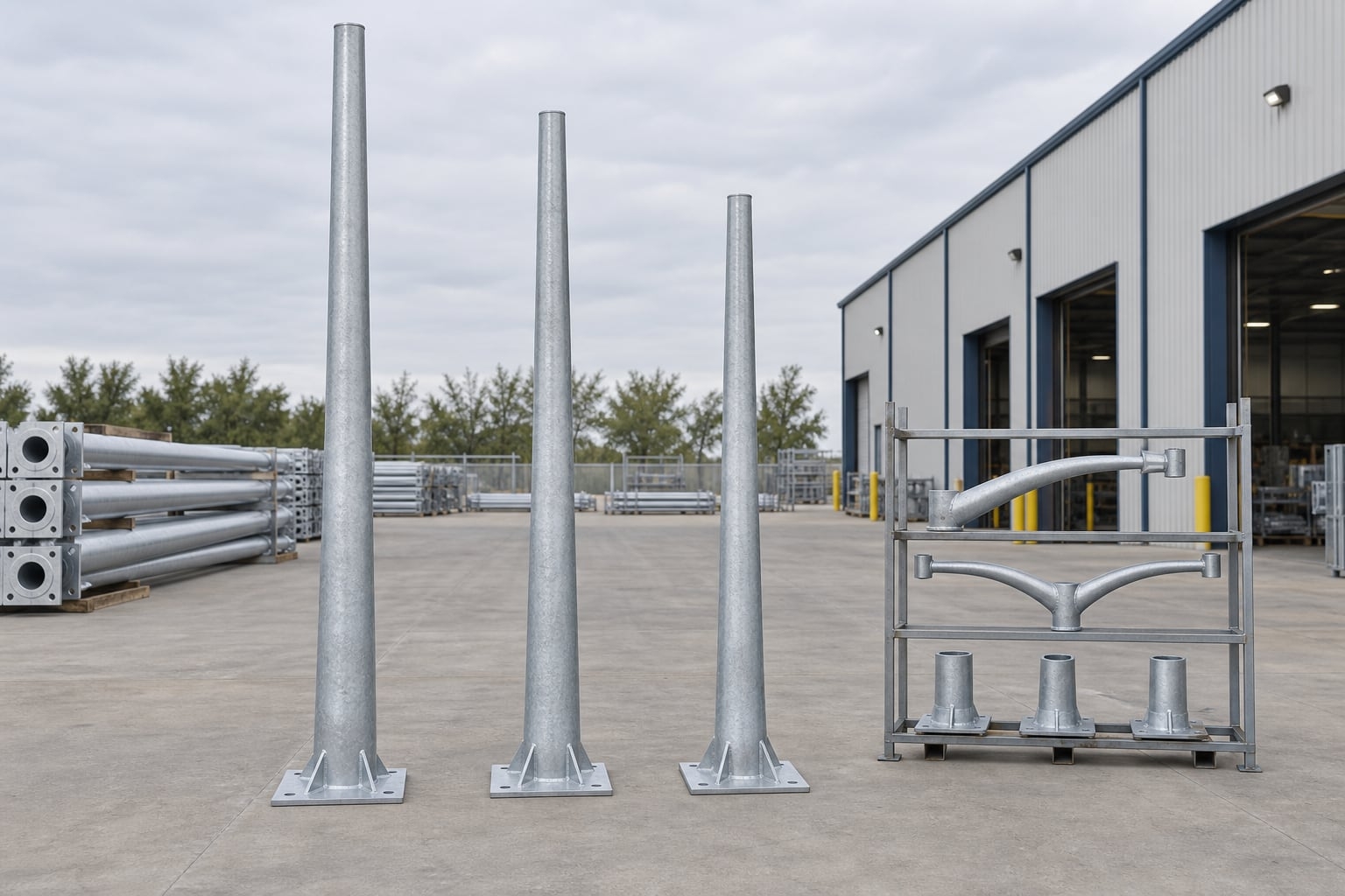


Configure a flange-mounted lighting pole around the required height, arm and luminaire loads, wind basis, shaft geometry, base plate, anchor assembly, foundation reactions, cable access and approved project documents.
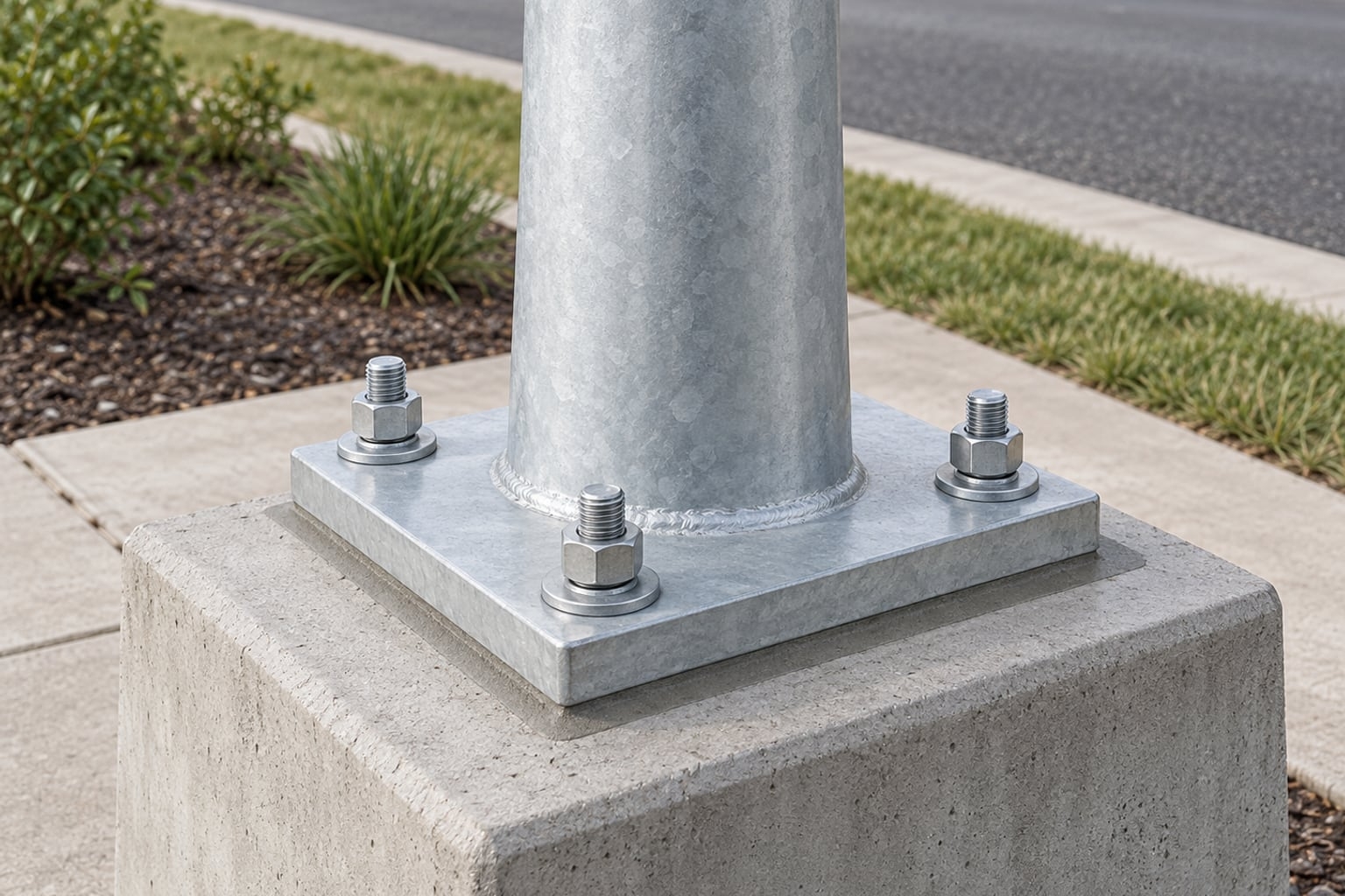
A flanged base galvanized steel light pole is a hollow steel shaft connected to a welded base plate. The plate sits on a prepared concrete foundation and is retained by an engineered anchor assembly. Shaft, plate, welds, anchors, nuts, washers, foundation reactions and cable route form one load path; they are not independent catalogue accessories.
The terms flanged base, base-plated and anchor-bolt pole describe a mounting concept, not a complete product. Height, shaft section, taper, wall schedule, steel grade, arm, luminaire, wind basis, plate geometry, anchor details and finish remain project-specific. Jieyao organizes those inputs by pole mark and develops a buildable supply package for approval.
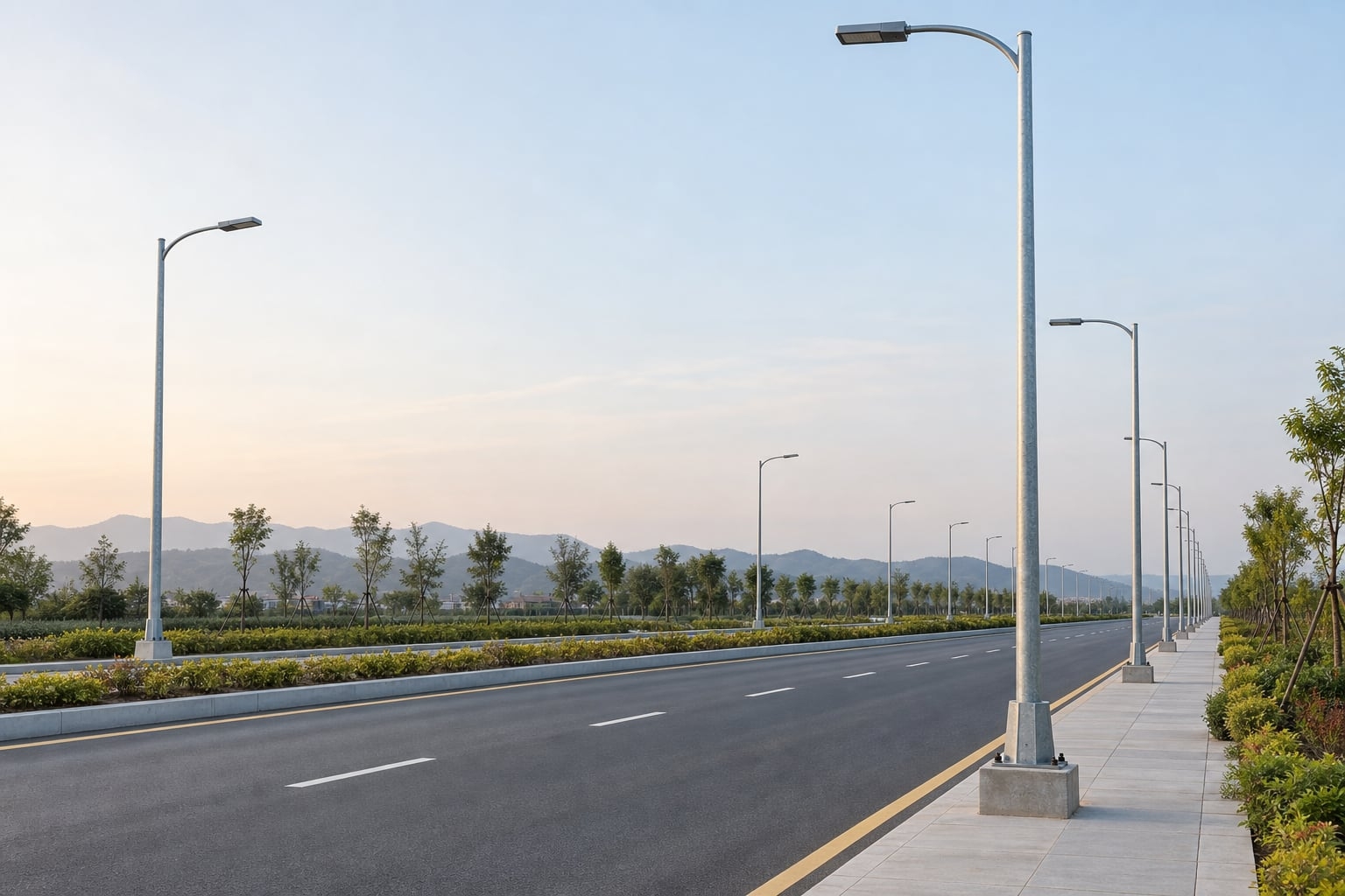
Base plate street light poles are widely considered for municipal roads, industrial parks, parking areas, campuses, ports, warehouses, commercial developments and highway-related lighting. A prepared foundation creates a defined civil interface and allows the pole to be erected after concrete condition, anchor position and conduit readiness have been checked.
The mounting concept does not decide the pole by itself. Two locations may use the same nominal height but require different arms, luminaires, exposure, clearance, collision protection and foundation reactions. Divide the project into pole marks rather than treating every position as identical, then keep those marks consistent across drawings, manufacturing records, packing and installation.
A flanged pole terminates above the foundation at a base plate and anchor assembly. A direct-burial pole extends below finished grade and transfers load through an embedded portion of the shaft and surrounding foundation material. The systems use different lower-shaft geometry, corrosion detailing, cable entry, erection sequence and civil coordination, so one should not replace the other without redesign.
Neither mounting method is universally better. Selection depends on the specification, soil and foundation concept, maintenance expectations, site workflow and exposure. Review the dedicated direct burial galvanized street light pole page when the shaft will be embedded. Use this page when a defined plate-and-anchor interface is required.
| Decision | Flanged base | Direct burial |
|---|---|---|
| Lower-shaft interface | Welded plate and approved anchor pattern | Approved embedded shaft length and below-grade detail |
| Civil information | Base reactions, plate drawing, anchor schedule and conduit position | Shaft embedment, foundation concept, cable entry and soil basis |
| Field hold point | Survey anchors, projection, support plane and conduit before lifting | Verify excavation, embedment mark, alignment and backfill method |
Mounting height, pole spacing, luminaire output, optical distribution, tilt, road geometry and maintenance assumptions should be coordinated through the photometric design. Height affects structural demand, visual scale, foundation reactions and service access. State whether the scheduled dimension means shaft length above the base plate, luminaire mounting height or total height including arm rise.
Height-specific pages such as the 8m galvanized pole, 10m single-arm pole, 10m double-arm pole, 12m highway pole and 15m highway pole can organize a schedule. Their nominal heights do not replace the project load and foundation review.
A flanged base can be coordinated with round, square or polygonal tapered shafts when the selected geometry, plate and weld detail form a coherent design. Shape affects appearance, section properties, openings, base-cover fit, arm transitions and dimensional conventions. Base type should not be used as shorthand for shaft shape.
Compare the round tapered pole and an octagonal galvanized section on the same height, arm, luminaire and wind basis. If a square tapered section is being considered, evaluate it on those same project inputs before choosing the profile. Record the selected section and measurement convention so the base, door, cover and replacement parts are not mixed.
Single arms, twin arms and post-top arrangements create different gravity, wind and torsional effects. Provide outreach, rise, inclination, tube size, connection, orientation and mass for every arm. Luminaire information should include the exact model, mounting interface, insertion length, mass, effective projected area, center of gravity and allowable tilt.
Fixture wattage alone is not structural data. A housing change can alter area, mass and lever arm even when electrical output is similar. Include signs, cameras, control boxes, banners and future attachments that belong in the design. When a top component changes after approval, repeat the compatibility and structural review before production or field installation.
A useful structural input set identifies the governing standard, basic wind parameter, exposure or terrain category, topographic condition, height reference, project risk provisions and relevant load combinations. The complete projected area and mass of all attachments must accompany those site parameters. A context-free wind-speed label cannot establish the suitability of a shaft or base.
Calculated reactions at the base are outputs of the approved pole design. They may include axial force, shear, bending moment and torsion in defined combinations. These reactions allow the responsible civil or structural designer to develop the foundation. If the pole configuration or design basis changes, the reaction schedule and foundation review must be revisited together.
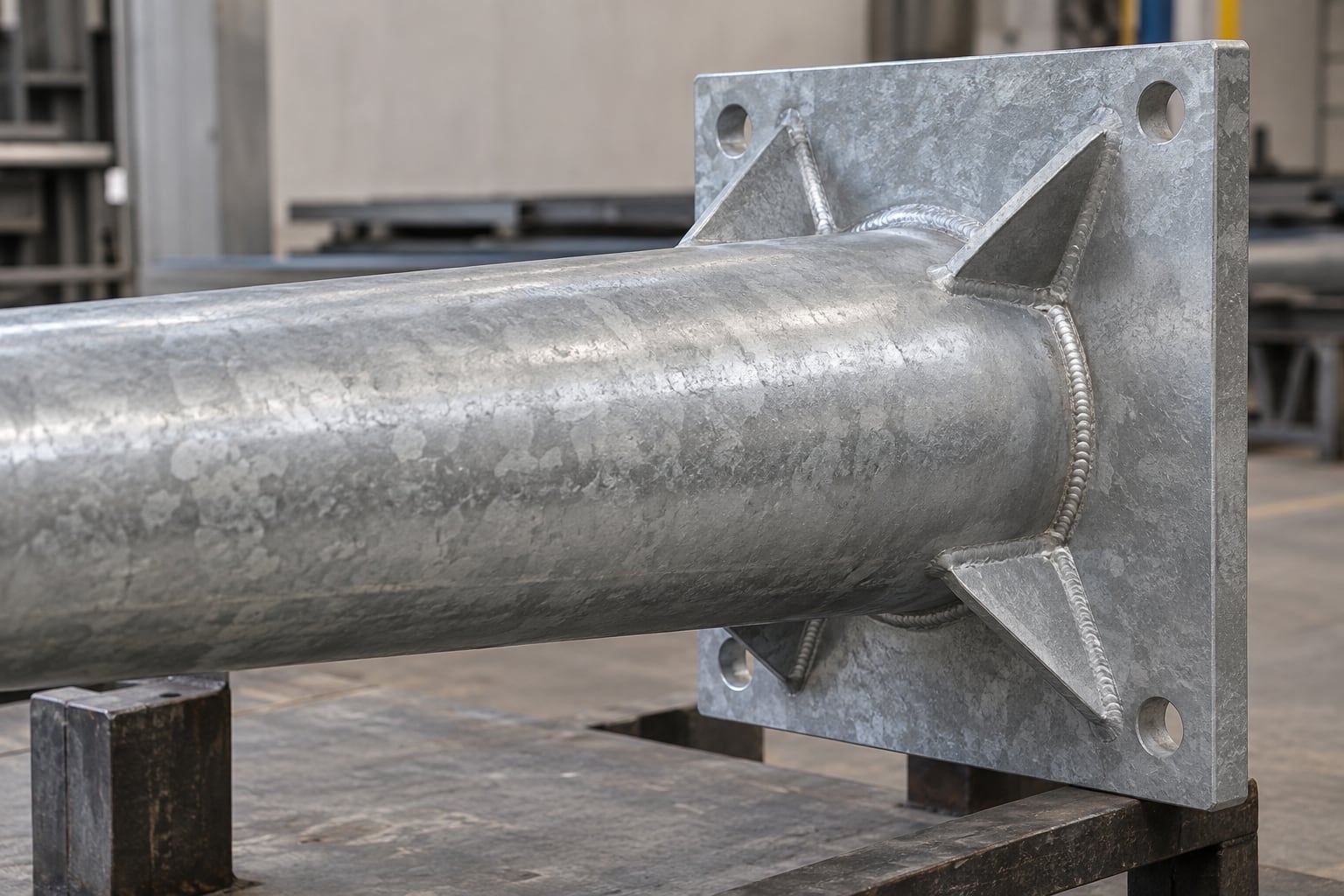
The shaft transfers load through the shaft-to-plate weld and any designed stiffening into the base plate. The plate distributes forces to the anchors and supporting foundation interface. Anchor rods, nuts and washers then connect the steel assembly to the concrete foundation and reinforcement system. Each element depends on the geometry and stiffness of the others.
A larger-looking plate is not proof of greater capacity. Plate thickness, footprint, hole position, edge distance, weld layout, shaft size, anchors, support condition and concrete design work together. Ask the supplier to identify the approved plate and anchor interface for each pole mark rather than comparing plate width or weight in isolation.
The base-plate drawing should define outside dimensions, thickness, shaft position, hole count, hole diameter, bolt circle or coordinate pattern, orientation, welds, stiffeners when used, cable opening and any cover interface. It should also identify which face or axis aligns with the arm and service door. Civil drawings should reference the same pole mark and revision.
Do not release a foundation from an early budget plate. Small changes to shaft size, hole position or required edge distance can invalidate installed anchors. Use a controlled hold point: approve the pole loads and base interface, then release the final foundation and anchor template. This sequence is less disruptive than correcting concrete after it is cast.
| Hold point | Evidence to exchange | Release decision |
|---|---|---|
| Pole configuration | Pole mark, height convention, shaft, arms, fixtures and site wind basis | Approve the structural input set before reaction data |
| Steel base interface | Reactions, plate revision, hole pattern, weld and anchor schedule | Match the supplier interface to the responsible foundation design |
| Before concrete | Released template, anchor projection, reinforcement and conduit layout | Civil team checks the coordinated drawing and field set-out |
| Before erection | Survey, concrete acceptance, anchor condition and cable-route check | Record discrepancies and resolve them before lifting |
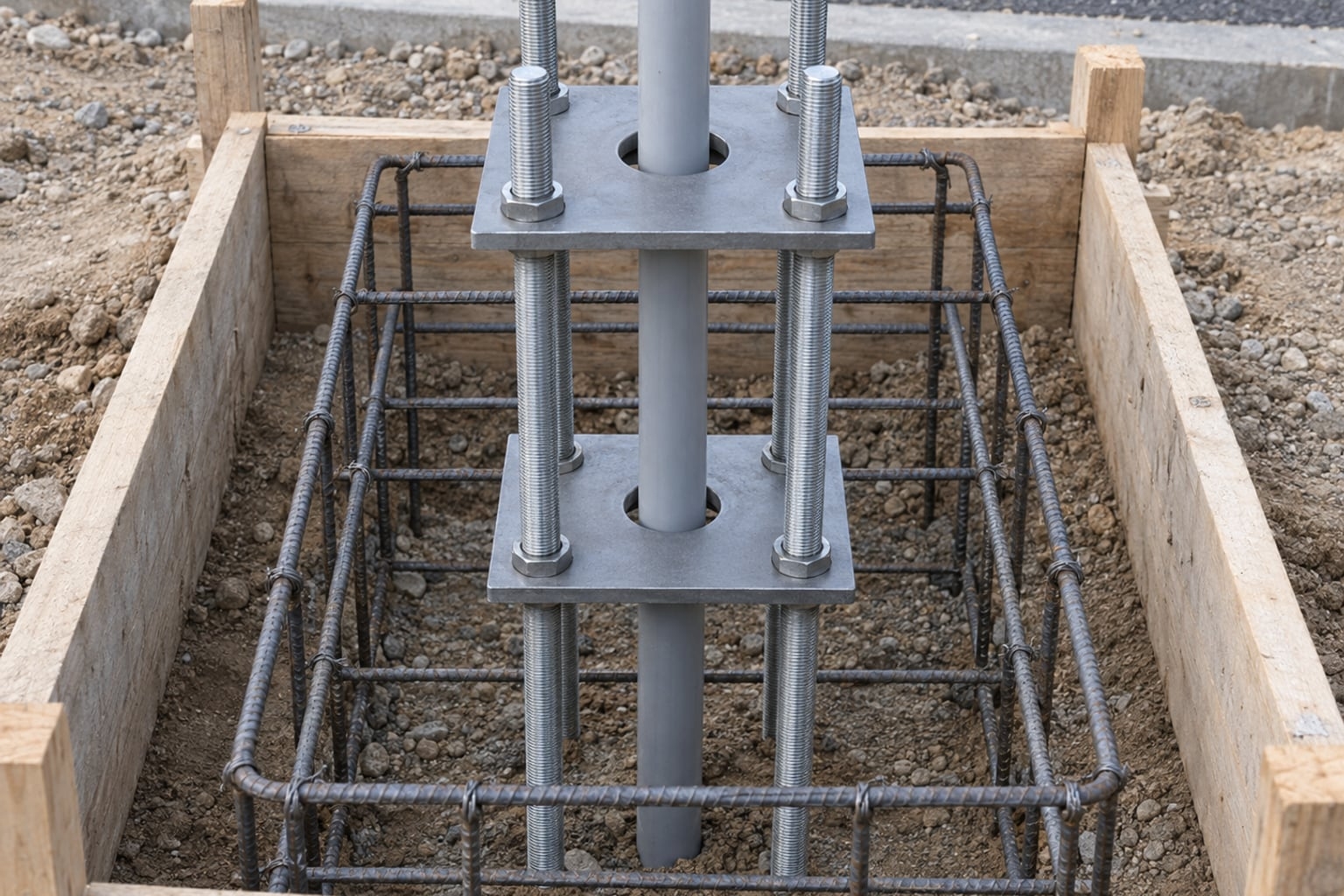
An anchor schedule should identify the accepted rod type, material requirement, diameter, effective length or embedment detail, thread length, projection, nuts, washers, template plates, corrosion protection and relationship to reinforcement. The foundation designer determines how the anchors develop the required forces in concrete under the applicable code and site conditions.
A diameter copied from another pole is not a complete anchor design. Rod spacing, edge distance, concrete strength, reinforcement, foundation geometry, load combinations and installation tolerance matter. Keep each anchor kit linked to its pole mark because similar-looking kits can differ in projection, template pattern or material.
Template plates hold anchor rods in the required plan position and orientation while reinforcement, conduit and concrete are placed. The assembly must be braced so it does not rotate, spread, lean or sink. Check the template against the released base-plate drawing before it enters the formwork, then check it again immediately before casting.
The template is an installation aid, not permission to force a mismatched pole over displaced anchors. Record centerline, elevation, projection, plumbness and orientation. Protect threads from concrete and impact. If the completed pattern is outside accepted tolerance, obtain an engineered disposition rather than bending rods on site.
Electrical conduit normally approaches the pole within the space permitted by the base plate and shaft opening. Its size, bend radius, elevation and exit position must accommodate the specified cables without interfering with anchors, templates, reinforcement, leveling arrangements or the shaft-to-plate weld. The cable path should avoid sharp edges and water traps.
Coordinate the conduit on both pole and foundation drawings. A generic centerline symbol may not show the real bend or connector. Confirm pulling access, spare capacity, earthing conductors and termination location. Cap the conduit during civil work and verify it is open before the pole is lifted; discovering a blocked route after erection creates unsafe and expensive rework.
The pole supplier can provide approved base reactions and the steel interface within the agreed scope. The responsible foundation designer then evaluates soil data, concrete, reinforcement, embedment, drainage, nearby utilities, edge conditions and governing requirements. These roles should be stated in the submittal so no critical check is assumed to belong to another party.
A standard foundation sketch cannot cover every soil and load condition. The street light pole foundation and anchor bolt design guide explains the information exchange in more detail. Final foundation size and reinforcement remain project decisions based on released reactions and site investigation.
Projects use different approved arrangements for leveling, bearing and grouting. The drawing should state the support plane, permitted leveling method, grout type where required, edge treatment, drainage and sequence for securing the pole. Do not assume that a gap, full bearing or grout thickness seen on another installation is acceptable for this design.
The final interface must transfer load as intended while allowing inspection and avoiding persistent water accumulation. Temporary wedges, loose shims or improvised packing should not become undocumented permanent supports. Civil and erection teams should use the current approved detail and resolve surface irregularities before lifting.
Nut arrangement, tightening method, sequence, target condition and any recheck follow the anchor design, fastener specification and approved installation procedure. A universal torque copied from a table without confirming rod material, diameter, lubrication, coating, thread condition and intended behavior can produce an incorrect result.
Keep anchor threads clean and protected. Nuts should run freely before erection, and washers should seat on suitable surfaces. Tighten progressively in the defined sequence while checking plumbness and plate behavior. Record the required installation check by pole mark when the project quality plan calls for it.
The base weld connects the shaft shell to the plate and carries the design forces into the anchorage system. Its type, size, continuity, preparation and any backing or reinforcement must be established by the approved design and fabrication procedure. The weld should be accessible for required examination before final coating.
Stiffeners may be used when the design calls for them, but their presence is not a universal quality indicator. Their geometry, welds and terminations must avoid poor fit-up and inaccessible coating pockets. Excessive grinding for appearance should not reduce the designed section. Repair and examination follow the specified quality plan.
Steel grade, wall thickness, shaft diameter or face width, taper, longitudinal seam, openings and base connection act together. A familiar grade name does not establish capacity without the complete section and fabrication basis. Material availability and forming behavior should also be considered before dimensions are frozen.
Show any change in wall schedule or shaft segment on the drawing. Keep plate and weld assumptions consistent with the selected shell. If the design changes from round to polygonal geometry, repeat the interface review rather than retaining a base plate simply because nominal height is unchanged.
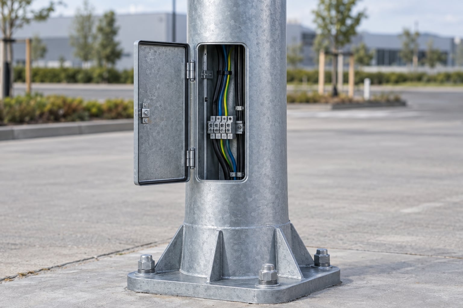
The service opening should provide workable access to terminals, protective devices or cable joints while remaining clear of the critical lower connection. Its elevation, orientation, dimensions, frame, reinforcement, cover, gasket, fasteners and earthing provision should appear on the approved pole drawing. The door should face a safe maintenance position.
Opening size and reinforcement influence the shaft and cannot be selected from convenience alone. Keep the door clear of traffic impact, barriers, landscaping and finished paving. Internal cables should be supported and separated as required, with smooth entry paths and no exposure to anchor hardware or sharp plate edges.
A removable cover can conceal anchors and create a cleaner visual transition, but it is not a structural repair. The cover must fit the shaft and plate, clear nuts and washers, allow specified drainage and remain removable for inspection. Paving and landscaping should not trap it or block the service door.
Water paths at the foundation top deserve explicit review. Avoid details that create a sealed pocket around hardware unless the system is designed for that condition. Do not use a cover to hide displaced anchors, unapproved packing, incomplete grout or corrosion. Complete and inspect the underlying installation before the cover is fixed.
Hot-dip galvanizing is normally coordinated after principal welding, approved openings and fabrication are complete. Venting and drainage, surface preparation, immersion, withdrawal and handling must suit the hollow shaft and attached plate. The applicable coating requirement, inspection method and permitted repair procedure should be stated in the purchase specification.
Plate edges, weld transitions, stiffeners, holes, threads and contact surfaces need attention because geometry affects zinc flow and inspection access. Coating thickness is not a universal online value; acceptance follows the applicable standard and project requirement. Avoid unnecessary field drilling or grinding that removes protection from the finished pole.
A compatible organic coating over galvanizing can provide a selected color and additional barrier layer for architectural or exposure requirements. Define the system, surface preparation, pretreatment, topcoat, color, gloss, texture, masking, repair and acceptance criteria. The coating supplier's compatibility instructions should govern the sequence.
Mating surfaces, threads, identification, earthing points and areas needed for assembly may require controlled masking. Pack coated components with padded separators and edge protection. A color sample should be approved under representative lighting before production when visual matching matters.
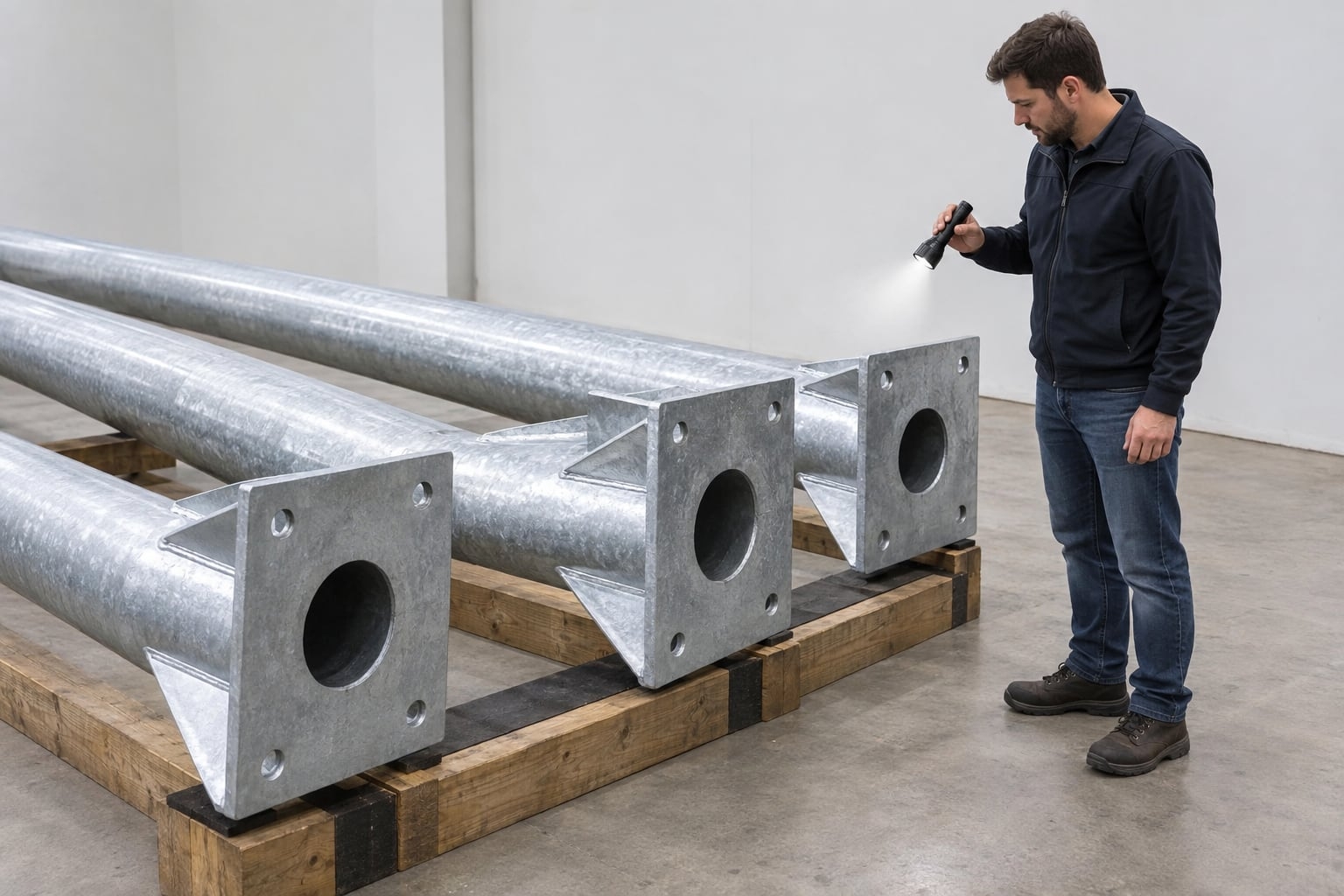
A proportionate inspection plan can cover material identity, shaft dimensions, taper, straightness, seam, openings, plate size and flatness, hole pattern, shaft position, welds, arm interface, galvanizing, accessories and pole marking. Define hold points and record format before production so acceptance does not depend on impressions at shipment.
Check the base against the approved anchor template or controlled dimensions. A pole that looks straight can still have a rotated hole pattern or incorrect door orientation. Link measurements and coating records to the pole marks and drawing revisions they cover. Trial assembly may be required when interfaces or project risk justify it.
A useful general arrangement identifies pole mark, height reference, shaft geometry, wall schedule, arm, luminaire interface, door, plate, anchor pattern, cable opening, orientation, finish and component list. Detail sheets clarify welds, stiffeners, templates, covers, joints and site assembly. Reaction schedules must match the configuration shown.
Review lighting, structural, civil and electrical information together. The street light pole shop drawing checklist provides a disciplined approval sequence. Close comments and update all affected sheets before releasing materials; approving one elevation does not automatically approve the foundation interface.
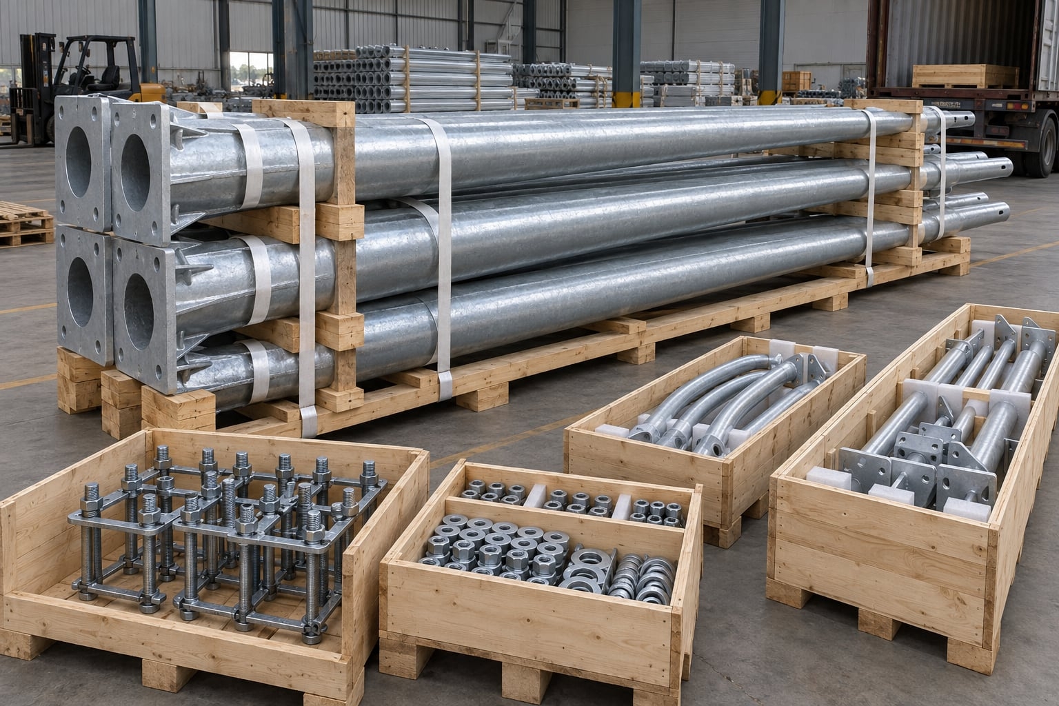
Long shafts need stable timber supports, padded separators and restraints suited to container handling. Protect plate corners, zinc surfaces, doors and top interfaces from point loads and rubbing. Anchor cages, nuts, washers, templates, covers, arms and small fasteners should be packed in distinct protected groups linked to the correct pole marks.
A complete packing list should identify bundles and accessory crates without relying on appearance. At receiving, count and inspect components before they are distributed around the site. Store shafts on level supports away from standing water, corrosive contamination and vehicle movement. Keep identification visible through erection.
Before lifting, verify the pole mark, foundation release, required concrete condition, anchor pattern, projection, thread condition, conduit access, support surface, surrounding clearance and current drawing. Confirm that nuts and washers match the approved assembly and that lifting equipment and method suit the pole mass and center of gravity.
Do not use the crane to force a plate over misaligned anchors. Stop and obtain a documented resolution if holes, rods, conduit or elevation do not match. Follow the approved site method statement for receiving, lifting, exclusion zones, plumb checks, wiring and handover.
Use approved lifting points and tag lines, keep personnel outside the suspended-load zone and lower the plate without damaging threads or cable ends. Establish the specified support arrangement, fit washers and nuts, and bring the pole to a stable condition. Check orientation and plumbness before completing the defined tightening and grout sequence.
Pull or connect conductors without scraping insulation across plate edges. Complete earthing, termination and door closure to the electrical specification. Install the arm and luminaire with the approved engagement, fasteners, tilt and cable path. Record final pole mark, orientation and installation checks where the quality plan requires them.
Finished paving, soil, planting and barriers should leave the base cover removable and the service door usable. Maintenance teams may need to inspect anchors, drainage, coating, door seals, terminals and cables. A visually clean installation that buries hardware or blocks the opening creates future difficulty. Coordinate finished levels and edge restraints before the civil works are closed.
Record the original luminaire, arm, plate and anchor information for later maintenance. Replacement fixtures can change mass, effective projected area, center of gravity and optical output even when they fit the spigot. New signs, cameras or banners also change loading. Review those additions against the recorded design basis before attachment.
The anchor pattern and plate may allow more than one apparent rotation, but the service door, arm and shaft faces still need the orientation shown on the approved drawing. Mark the road side, door side or arm axis on templates and pole components when visual judgment alone could cause mistakes. The setting-out drawing should use the same reference.
Orientation affects more than appearance. It can determine safe maintenance access, cable routing, arm alignment, directional section behavior and clearance from barriers or traffic. Check rotation before final tightening and before grout or paving makes adjustment difficult. Photograph or record the completed mark where project handover procedures require it.
A damaged pole cannot be replaced safely from height and base width alone. Confirm the original shaft section, wall schedule, plate footprint, hole pattern, anchor condition, arm, fixture loads, wind basis, door orientation and finish. Existing foundations and anchors should be inspected by the responsible project team before a replacement is ordered.
If original records are incomplete, obtain controlled site measurements and identify uncertainty. Do not slot holes, enlarge plate openings or heat-bend anchor rods as a routine fit-up method. A replacement proposal should state which existing interfaces are retained, which are verified and which require civil modification or engineering approval.
Common omissions include height without a reference point, fixture wattage without mass or EPA, wind speed without exposure and standard, plate size without anchor data, anchor diameter without material and embedment, and a civil drawing based on an unapproved hole pattern. Another error is assuming every pole of one nominal height uses one base.
Use controlled milestones: freeze the lighting loads, confirm the structural basis, approve the pole and plate interface, release the foundation, verify installed anchors and then erect. Ask suppliers to list assumptions and exclusions. Clear open items are safer than precise-looking dimensions based on missing project information.
The required handover package can connect as-built pole marks with approved drawings, calculation or reaction schedules, material and coating records where specified, dimensional inspections, packing information and site installation checks. The exact scope follows the contract. Clear indexing matters more than collecting unrelated documents.
Remove superseded drawings from the installation set and identify which records cover each batch or pole mark. Preserve anchor-template data and luminaire loads because they support later replacement decisions. A maintenance team should be able to trace the installed shaft, base interface and top equipment without reconstructing the original procurement process.
Align pole marks, shaft geometry, steel, arms, luminaire interfaces, plates, anchors, templates, covers, doors, terminals, galvanizing, drawings, calculations, inspection, packing and delivery before comparing offers. A lower commercial value may omit the anchor kit, documentation, a required finish operation or inspection point rather than represent better value.
Require each proposal to state its design assumptions, supplied interfaces and responsibilities. Compare reaction data and drawing scope, not only nominal height and plate dimensions. The wider street light pole range can organize mixed shapes, mounting types and heights while this page retains ownership of flange-mounted procurement questions.
Send the application, location, quantity by pole mark, mounting-height definition, lighting layout, arm geometry, luminaire model and interface, mass, EPA, center of gravity, wind basis, preferred shaft shape, door orientation, electrical arrangement, finish, inspection, documentation and delivery constraints. Civil or architectural drawings should be included when they control clearances or appearance.
For the base, include the foundation concept, available civil drawings, required plate orientation, anchor-supply scope, conduit position, cover preference and governing standard. If information is preliminary, identify it as open. A supplier can organize missing decisions without presenting provisional dimensions as final and can show the approval hold points in the quotation.
Jieyao begins with the pole schedule, lighting coordinates, luminaire and arm data, wind basis, shaft preference, base concept, finish and transport route. The review separates fixed requirements from options and missing inputs. A project-specific proposal then connects the offered pole, plate, anchors, drawings, inspection and packing to the same pole marks.
The objective is an approvable and buildable interface, not a universal online base size. Final shaft, plate, anchor, weld and reaction details follow the governing standard and approved project basis. Send the available information through the contact page; clearly recorded questions can be closed before civil release and production.
The pole shaft is welded to a plate and secured to a concrete foundation by an anchor assembly.
No. A direct-burial shaft extends below grade; a flanged pole ends at a plate above the foundation.
No. Plate geometry follows the shaft, loads, anchors and approved support detail.
The number and pattern are project-specific and must match the approved plate and foundation design.
The responsible foundation designer uses the approved pole reactions, soil data and project code.
Yes, when the shaft, plate, weld, cover and anchor interface are engineered together.
No. Luminaire, arm, wind, site, shaft and foundation inputs are also required.
They can be included when their scope, pattern and pole-mark identification are agreed.
Not universally. Follow the approved support, leveling, grout and drainage detail.
Yes, when it clears the hardware, permits drainage and remains removable for inspection.
Send the governing standard, wind parameter, exposure, topography, height and all attachments.
Send the pole schedule, lighting layout, loads, wind basis, base concept, finish and delivery scope.
Send your pole schedule, lighting layout, luminaire and arm data, wind basis, foundation concept and finish requirement. Jieyao will organize the open items and prepare a project-specific configuration for technical review.
Contact Jieyao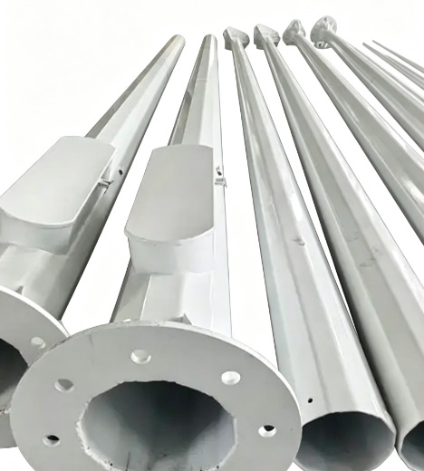
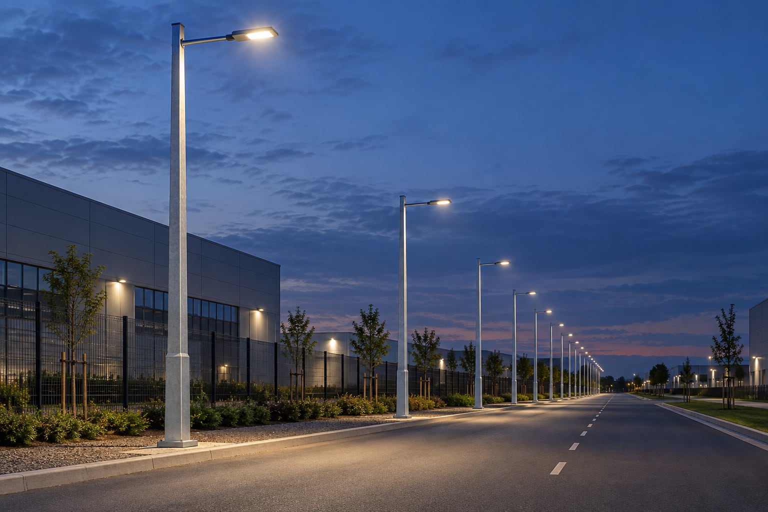
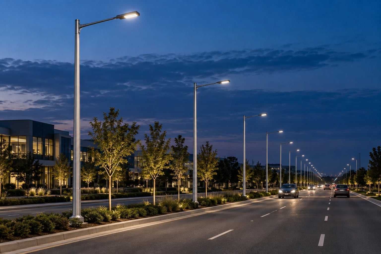
Plan a parking lot light pole layout with photometric files, protected pole locations, glare control, structural loads, foundations and maintenance access. Height and spacing are project-specific.
Learn how to choose lighting poles for airports and ports. Understand key selection standards including wind load resistance, corrosion protection, pole height, material choice, and safety requirements for aviation and marine environments.
Compare hot-dip galvanizing, direct-to-steel paint and compatible duplex coatings for street light poles by exposure, detailing, inspection and repair scope.
Compare galvanized steel, aluminum and stainless steel light pole assemblies by structural design, fabrication, corrosion control, finish, handling and inspection evidence. Select materials for the project exposure and approved supply scope.
Compare single arm and double arm street light poles for roads, highways, parking areas, and municipal projects. Learn the differences in lighting coverage, installation cost, application scenarios, and how to choose the right street light pole for long-term project performance.
The best pole for solar street lights depends on wind load, environment, and project scale. Learn when to choose steel, aluminum, or galvanized steel poles for different outdoor lighting applications.
Discover the life expectancy of street light poles based on materials like steel, aluminum, and concrete. Learn how climate, installation quality, and maintenance affect pole lifespan in real outdoor lighting projects.
Learn how to install a solar street light with pole step by step, including foundation construction, pole erection, wiring, and system testing. A practical guide for road lighting, parking lots, and outdoor solar lighting projects.
We primarily use high-strength carbon steel (Q235/Q345/ASTM A36). We also offer premium aluminum alloy and stainless steel poles specifically for coastal regions.
Tapered poles are aesthetic with low wind resistance; cylindrical poles are more cost-effective; polygonal poles (usually 8/12/16 sides) offer the highest structural strength, ideal for high mast lighting.
Our engineers perform mechanical calculations based on your local wind speed data, adjusting wall thickness and base design to ensure the poles can withstand winds up to 160km/h.
It typically ranges from 3mm to 12mm, depending on the pole height, weight of the fixtures, and local wind load requirements.
This is an anti-corrosion process of immersing steel in molten zinc. It provides over 25 years of maintenance-free rust protection in standard outdoor environments.
Yes. We provide complimentary foundation reference drawings, including concrete depth, rebar specs, and bolt positioning data.
We follow AWS welding standards and use Ultrasonic Testing (UT) or Magnetic Particle Testing (MT) to ensure welds are free of pores or cracks.
We hold ISO 9001 (Quality), ISO 14001 (Environmental), and CE certification (EN 40) specifically for the European market.
Yes. We can produce sample poles for craft and color confirmation, though sample shipping costs are typically covered by the client.
Steel poles are lighter, easier to transport and install, have a long lifespan after galvanization, and offer high scrap value, making them more eco-friendly.
Galvanized poles are virtually maintenance-free. We recommend checking anchor bolt tightness and the powder coating surface every 3-5 years.
We provide touch-up paint with each shipment. Simply clean the scratch and apply the paint to restore the appearance.
No. Base plate size and hole spacing are designed based on pole height and stress loads. We provide detailed dimensional drawings for each order.
These are accessories (like anti-climb spikes) installed on the lower section of the pole to prevent unauthorized climbing and enhance security.
Yes. We can flexibly adjust section lengths (e.g., 6m+6m or 5m+7m) based on logistics constraints and on-site installation conditions.
Contact Us
Get a custom lighting solution and quotation for your project. Outdoor lighting manufacturer in Yangzhou, ChinaAbout Jieyao LightingYangzhou Jieyao Lighting Equipment Co., Ltd. is an outdoor lighting manufacturer focused on solar street light systems and high mas... Do you have any questions or requests?
Email: jay@jieyaolighting.com

Click to Chat.
Im online now.