A 15m Highway Lighting Pole Is a Project-Defined Structure
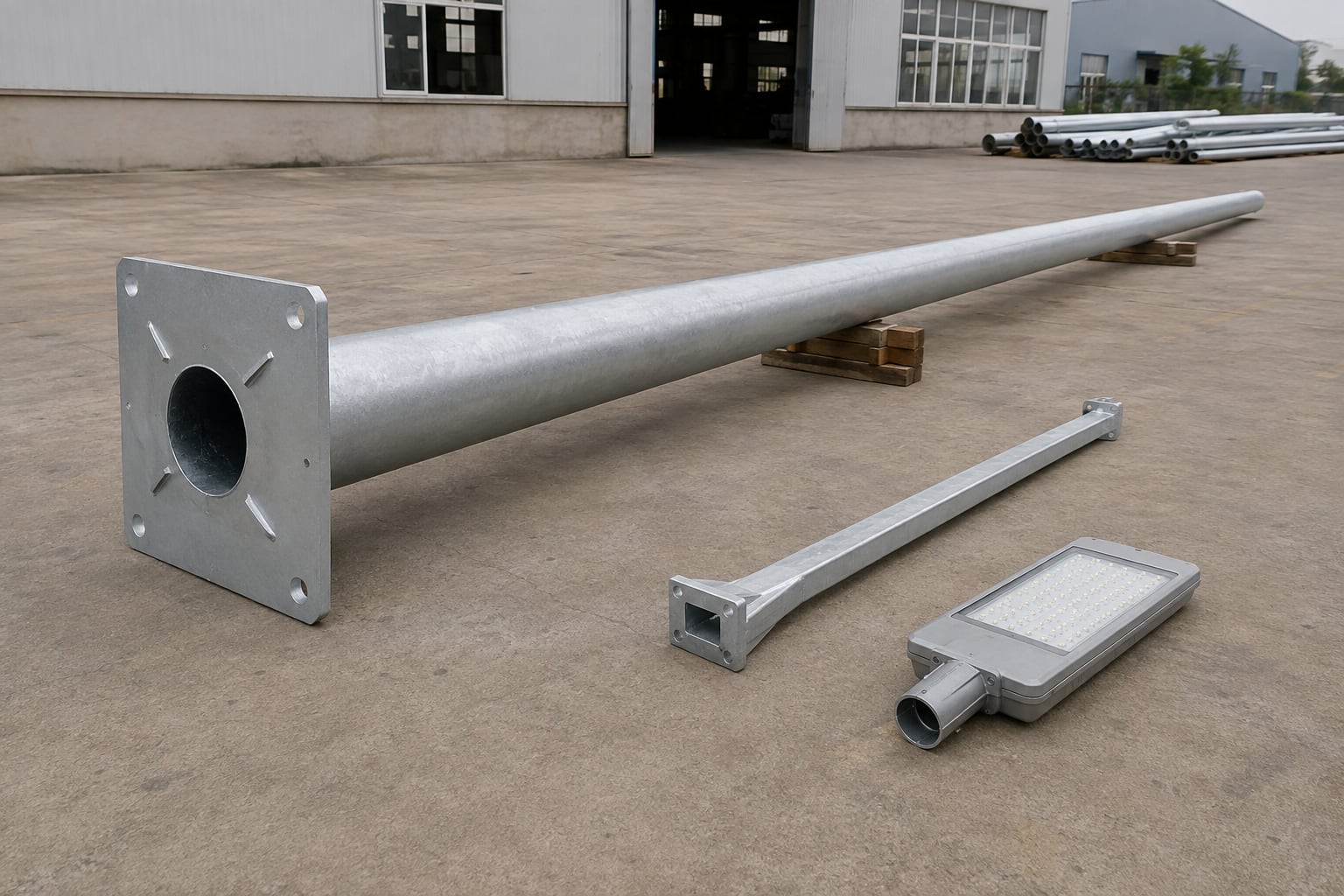
A 15m galvanized highway lighting pole is not selected by height alone. At this scale, a change in luminaire size, arm reach, terrain exposure, shaft section or door location can materially affect the structural demand. The practical product is therefore a coordinated assembly: tapered steel shaft, arm or top adaptor, luminaire interface, access opening, base plate, anchor system, internal cable route and surface protection.
Jieyao prepares the pole around the buyer's road layout, photometric design and governing project requirements. Production dimensions are recorded on an approved drawing rather than inferred from a catalogue photograph. This approach helps procurement teams compare offers on the same basis and gives civil, electrical, transport and installation teams a common set of interfaces.
The phrase "15 meter pole" also needs a defined reference. It may describe the shaft above the base, the luminaire mounting height or the overall height including an arm rise. Those values are not automatically identical. The requested reference should appear on the inquiry and final drawing.
Procurement usually works best when the pole schedule, luminaire schedule and road plan are reviewed together. The schedule identifies quantities and item marks, the fixture data defines the top load and connection, and the plan explains where each arm must point. Treating those documents as one coordinated input helps prevent a structurally suitable shaft from arriving with the wrong outreach, door orientation or anchor template. It also gives the factory a clear basis for marking mixed shipments.
Typical Road Applications
Highways and expressways
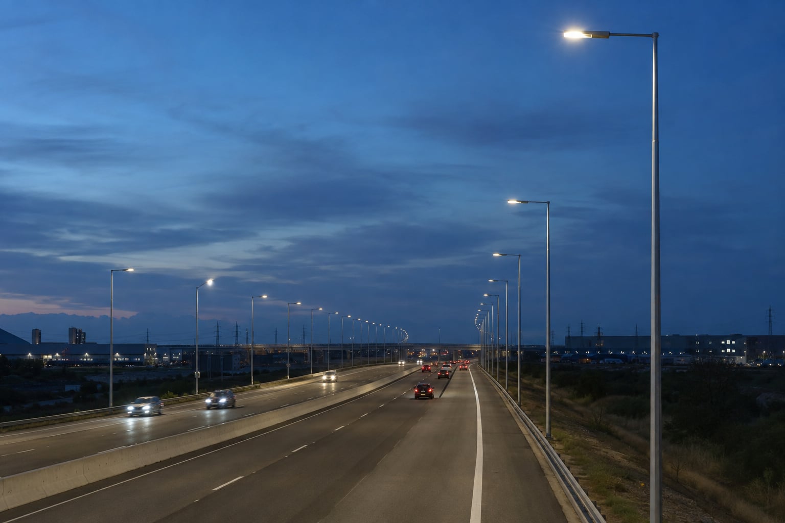
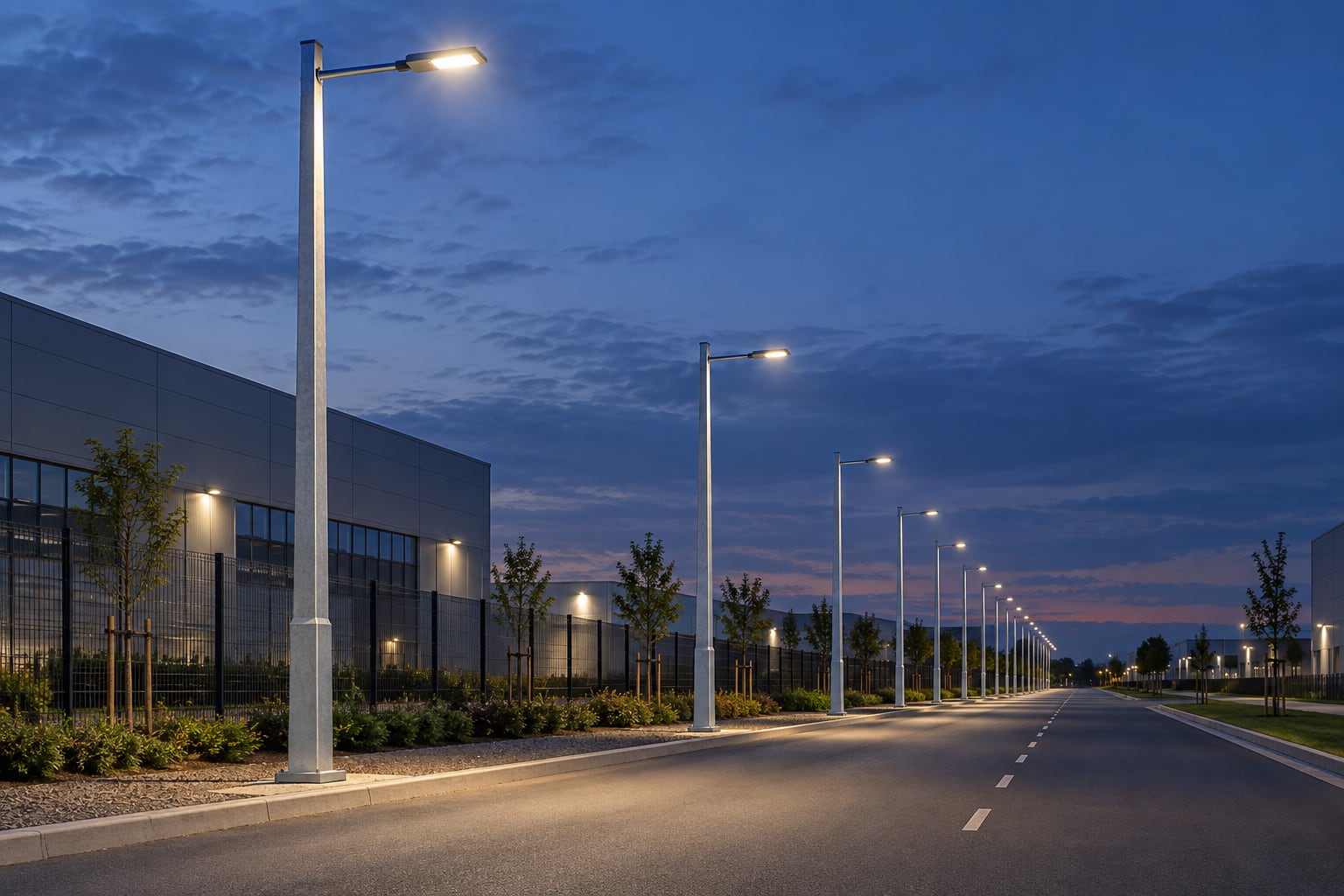
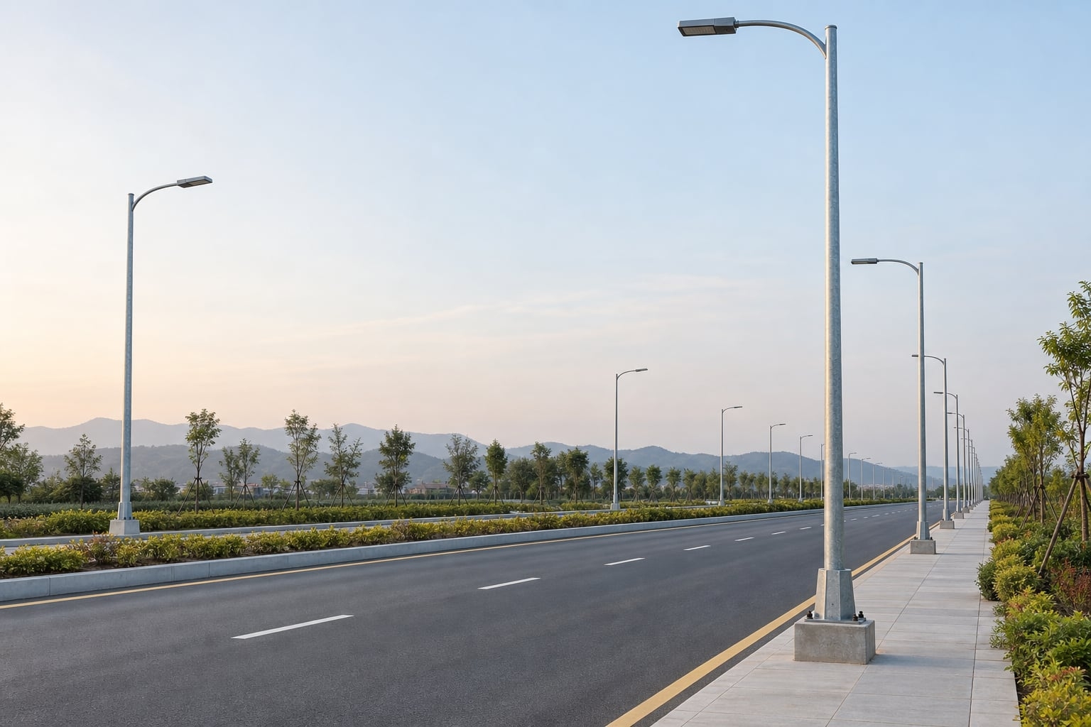
Tall roadside poles may support wider optical coverage on mainline sections, ramps and merge zones where the lighting calculation selects a 15m mounting position.
Wide arterial roads
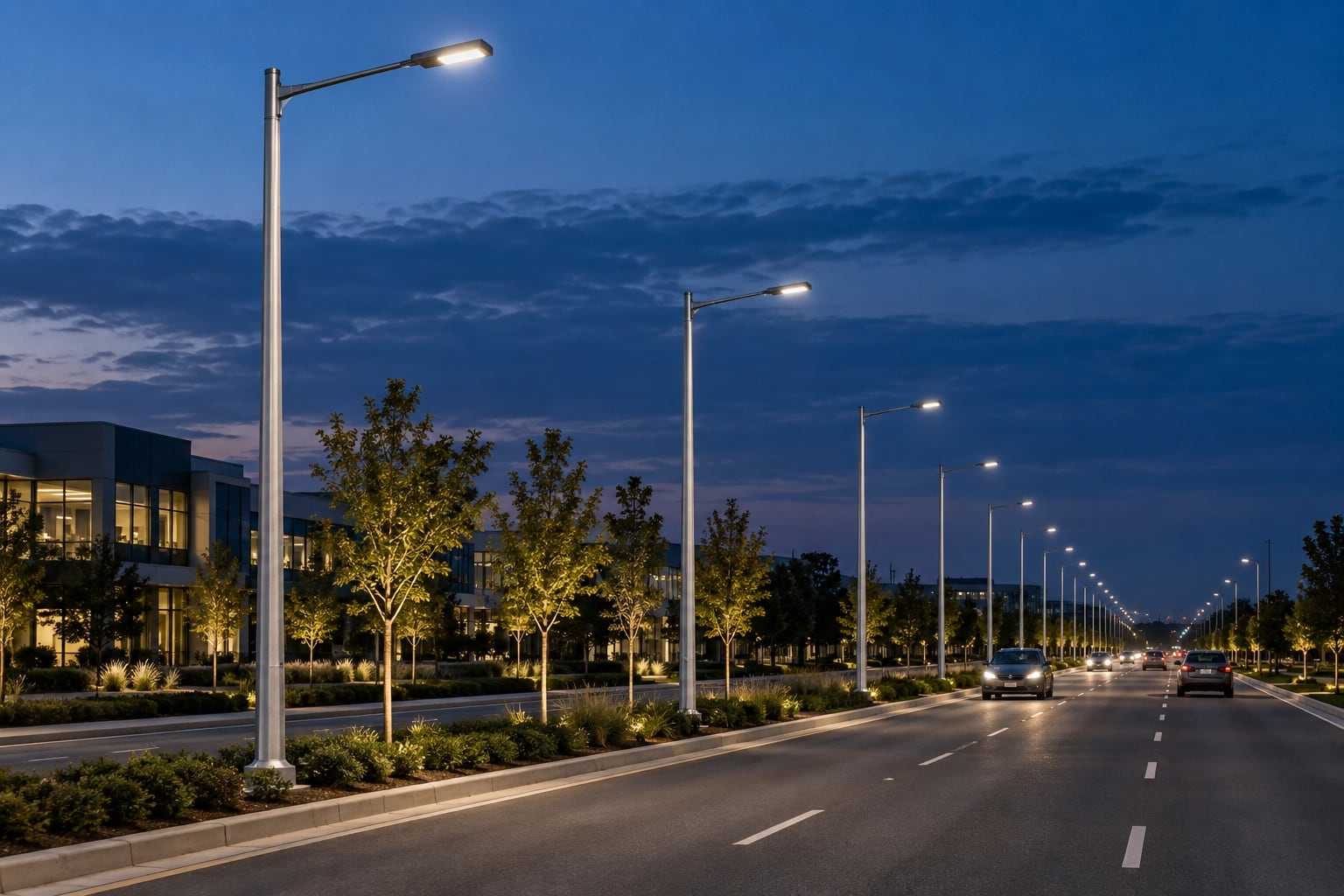
Multi-lane urban corridors can use roadside or central-median arrangements, subject to glare, uniformity, clear-zone and maintenance requirements.
Interchange approaches
Changing carriageway geometry may call for different arm directions, mounting offsets and pole stations while keeping a coordinated family of shaft details.
Port and logistics roads
Truck routes and exposed access roads may add corrosion, vehicle-clearance and transport-facility requirements to the conventional pole specification.
Industrial corridors
Large sites may need road lighting around gates, distribution routes and perimeter connections without moving to a lowering-ring high-mast system.
Large transport precincts
Airport landside roads, terminal approaches and parking circulation routes can use this pole type when photometric and authority reviews support it.
Project-Configurable Specification
| Item | Configurable scope | Information used to decide |
|---|
| Height reference | 15m shaft, mounting height or defined overall height | Road drawing, luminaire position and arm rise |
| Steel | Q235B, Q355 or approved specified equivalent | Design demand, project material rules and availability |
| Shaft form | Tapered octagonal or project-defined polygonal section | Structural calculation, tooling, appearance and joint geometry |
| Shaft construction | One-piece or engineered sectional arrangement | Galvanizing, shipping route, container and erection plan |
| Top arrangement | Single arm, double arm, short outreach or custom adaptor | Photometric layout, luminaire interface, load and clearance |
| Base connection | Flanged base plate with project-specific anchors | Calculated reactions and civil foundation interface |
| Electrical access | Reinforced lockable door, cable opening and earthing point | Equipment scope, cable route and maintenance access |
| Surface protection | Hot-dip galvanizing; optional compatible color system | Specified standard, environment and appearance |
| Submittals | Drawings, material and inspection records as agreed | Tender, approval and inspection plan |
| Packing | Protected bundles, crates and identified loose parts | Section length, transport method and unloading sequence |
Final values are set by the approved project documents. This table describes available coordination scope, not a universal certified configuration.
Confirm What the 15m Dimension Means
A clear dimension reference prevents errors in photometric layout, fabrication and installation. If 15m is the pole shaft length above the base, an upswept arm can place the luminaire higher. If 15m is the photometric mounting height, shaft and arm dimensions must be selected to reach that elevation. If the project measures total installed height, base level, bracket rise and fixture position all need to be shown.
Useful drawings identify finished foundation level, top of base plate, shaft length, arm connection, luminaire center or mounting axis and any vertical rise. The same terminology should be used in the quotation, purchase order and shop drawing. This small clarification is especially important when the road designer, buyer and installer use different height conventions.
Conventional Pole or High Mast
A 15m highway light pole can be tall without being a high mast. A conventional pole normally carries one or a small number of luminaires on fixed arms or a fixed head. A high-mast system typically uses a multi-luminaire headframe and may include a lowering mechanism, winch, cables, latches and service controls. These are different products with different maintenance and safety requirements.
The choice should follow the road geometry, target illuminance and uniformity, glare limits, obstruction clearances, maintenance method and lifecycle plan. A conventional 15m pole may suit a linear carriageway. A large interchange or apron may justify a high mast after a lighting study. See the comparison guide on street poles versus high masts for highway interchanges.
15m conventional pole or high mast: scope questions to resolve| Decision field | 15m conventional highway pole | High-mast system |
|---|
| Lighting arrangement | One or a small fixed fixture arrangement along a linear corridor | Multi-luminaire head serving a broad area after photometric study |
|---|
| Maintenance concept | Access equipment and traffic control planned for fixed luminaires | Fixed or lowering head with defined winch, cable, latch and operating procedure |
|---|
| Structural inputs | Shaft, arms, luminaires, accessories, wind basis and base interface | Mast, headframe, every fixture, operating equipment, dynamics and base interface |
|---|
| Release evidence | Road layout, photometric model, pole schedule and approved shop drawing | Area study, head schedule, operating design and approved mast/foundation package |
|---|
Start With Road Geometry and Photometric Design
The lighting calculation should establish whether 15m is appropriate before the steel pole is finalized. Road width, lane count, median position, shoulder, curvature, junctions, barriers, signs and adjacent properties influence pole spacing and luminaire aiming. Pavement classification and the required lighting criteria also affect the optical solution.
The supplier should receive the proposed pole coordinates, mounting side, arm orientation, outreach, fixture model and aiming where applicable. Those inputs connect the photometric design to the mechanical arrangement. Changing from a single roadside fixture to a double median arrangement after the shaft is designed can alter wind area, torsion and base reactions.
Where the lighting calculation remains preliminary, the quotation should identify the assumed fixture and bracket envelope. The final photometric model can then be checked against that envelope before the drawing is approved. This preserves design flexibility without hiding which load case was used for the proposed 15m galvanized highway lighting pole.
Luminaire Mass, EPA and Mounting Position
LED wattage is not enough information for structural coordination. Jieyao requests the luminaire mass, dimensions, effective projected area or sufficient geometry to establish it, center of gravity, mounting opening, insertion depth, locking method and planned tilt. Accessories such as cameras, signs, sensors or communication devices must also be listed.
Effective projected area, often abbreviated EPA, relates exposed shape to wind loading. A light but broad fixture can create more wind demand than a compact heavier one. Distance from the shaft centerline adds leverage, so the final arm reach and fixture position matter. Where several approved luminaires remain under consideration, the pole design basis should state the envelope used for checking.
Single Arm, Double Arm or Bracket Arrangement
A single arm commonly serves a roadside installation, while a double arm can serve opposing carriageways from a median. Custom arrangements may address a service road, asymmetrical median or interchange gore. The drawing should define outreach, rise, angle, tube or fabricated section, connection, cable path and fixture tenon.
Longer or heavier arms increase bending and exposed area. Unequal arms can add torsion. Detachable arms can reduce the shipping envelope and simplify replacement, but the bolted or sleeved connection must be positively secured and protected against corrosion. Field-drilled adaptors or improvised clamps should be avoided because they can damage zinc and create loads not represented in the approved design.
Wind Basis and Structural Inputs
A wind-speed number without its standard and definition is incomplete. Codes can use different averaging periods, return periods, importance factors, gust treatments and load combinations. Terrain exposure, open water, embankments, escarpments and bridge elevation can change the pressure applied to the pole and equipment. The inquiry should identify the governing standard, wind-speed definition, terrain or exposure category, topography and any authority-specific criteria.
The structural model also needs pole height reference, arm geometry, luminaire mass and EPA, accessories, shaft joints, door opening and support condition. A buyer comparing offers should check that suppliers used the same inputs rather than comparing only wall thickness. The wind-load and EPA RFQ checklist provides a practical input framework even when the requested product is a conventional pole.
Important: no context-free wind capacity is offered on this page. The applicable configuration is established from the named code, site exposure, full equipment arrangement and approved calculation or design basis required by the project.
Shaft Form and Taper
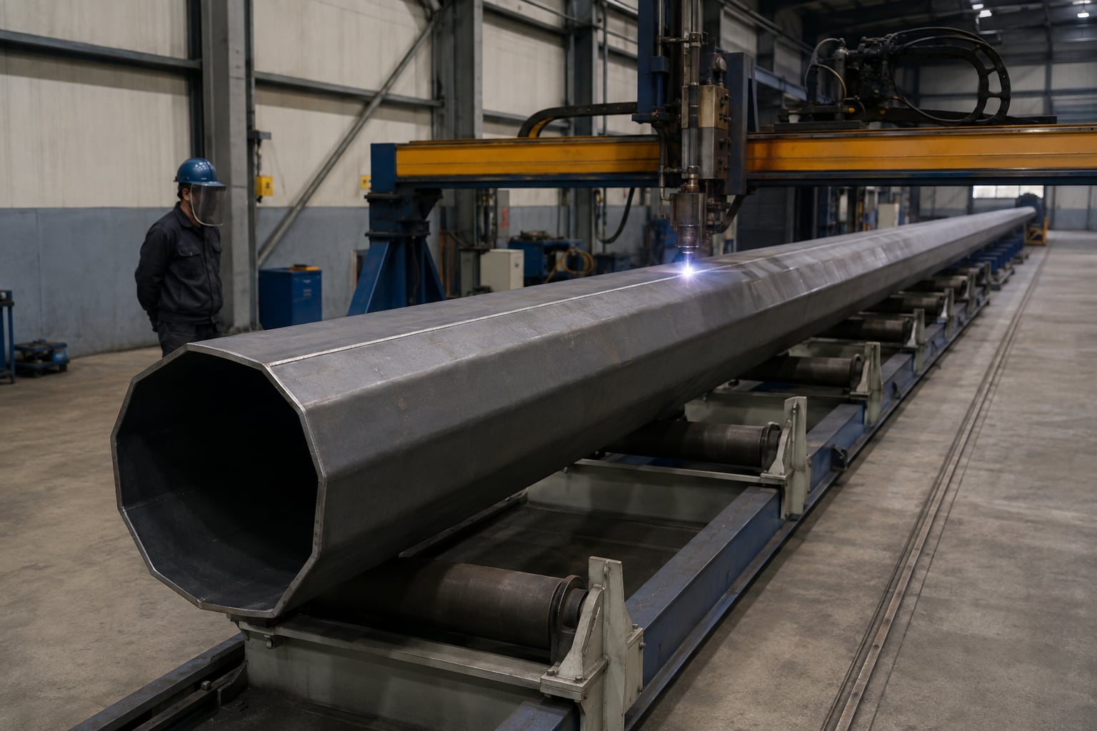
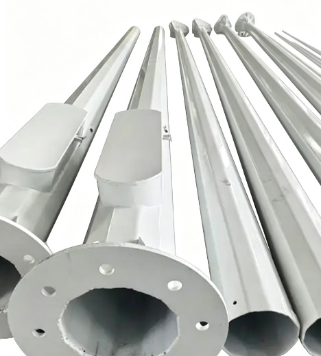
A tapered polygonal shaft places a larger section near the base, where global bending demand is generally higher, and reduces dimensions toward the top. Octagonal geometry is common, while another polygon count may be selected by design or specification. The developed plate is press-brake formed and closed by a longitudinal weld.
Key drawing values include top and bottom dimensions across flats, taper, plate schedule, section lengths, joint location, seam orientation, door position and arm orientation. These values work together. A nominal diameter or wall thickness copied from another project is not a substitute for the complete shaft geometry.
One-Piece or Segmented Shaft
A one-piece 15 meter shaft reduces field assembly but requires suitable fabrication handling, galvanizing capacity, road transport and lifting access. Depending on the route and destination, the length may be difficult to place in standard shipping arrangements. A segmented shaft can improve handling and container planning, but it adds a controlled joint and assembly procedure.
The decision should be made before the shaft is engineered. Section breaks cannot be added arbitrarily after design because profiles, overlap, local stresses and transport supports must be coordinated. The buyer should provide destination port limits, inland route constraints, site access and available erection equipment during the quotation stage.
Slip-Joint and Flange-Joint Decisions
A tapered slip joint uses compatible nested profiles and a specified engagement. The shop drawing should show nominal overlap, orientation marks and the approved method for pulling or pressing sections together. Profile control matters: excessive mismatch can prevent full engagement, while uncontrolled impact can deform the shaft or damage galvanizing.
A bolted flange joint may be used where a removable connection is required, but it changes the local geometry, fastener arrangement and appearance. Bolt access, preload method, corrosion protection and inspection must be practical. Neither joint type should be chosen only for packing convenience; the structural, manufacturing and site consequences should be reviewed together.
Steel Grade and Plate Schedule
Q235B and Q355 are common options for fabricated steel poles, subject to project acceptance and material availability. Q355 provides a higher nominal yield strength, but grade alone does not determine an adequate pole. Local buckling, forming, weld details, door reinforcement, joint behavior, base connection, fatigue-sensitive features and serviceability checks remain relevant.
If an EN, ASTM or other material system is specified, equivalence should be reviewed using mechanical properties, chemistry, thickness range, forming and welding requirements. Production material records should identify the plate supplied for the order. The wall schedule is then derived with the complete shaft geometry and load basis, not selected from height alone.
Longitudinal Welding and Straightness
After forming, the polygonal shaft is closed by a longitudinal seam. The welding procedure, fit-up and inspection scope should match the material, thickness and project quality plan. Start and stop areas, transitions and local attachments require controlled workmanship. Grinding should not remove necessary section thickness or create sharp surface transitions.
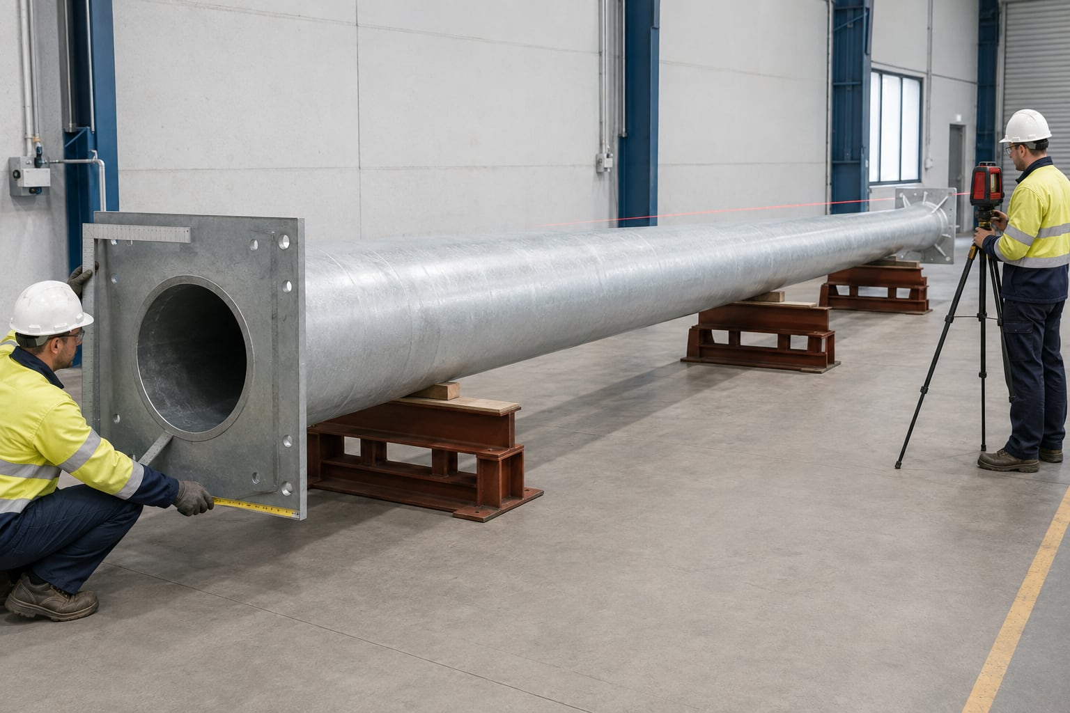
Straightness, twist and profile dimensions are checked before the pole is released for coating. For a sectional shaft, mating geometry also needs verification. These checks support arm alignment and site erection; a pole that is difficult to align at ground level will become more visibly displaced at the luminaire elevation.
Base Plate and Anchor Interface
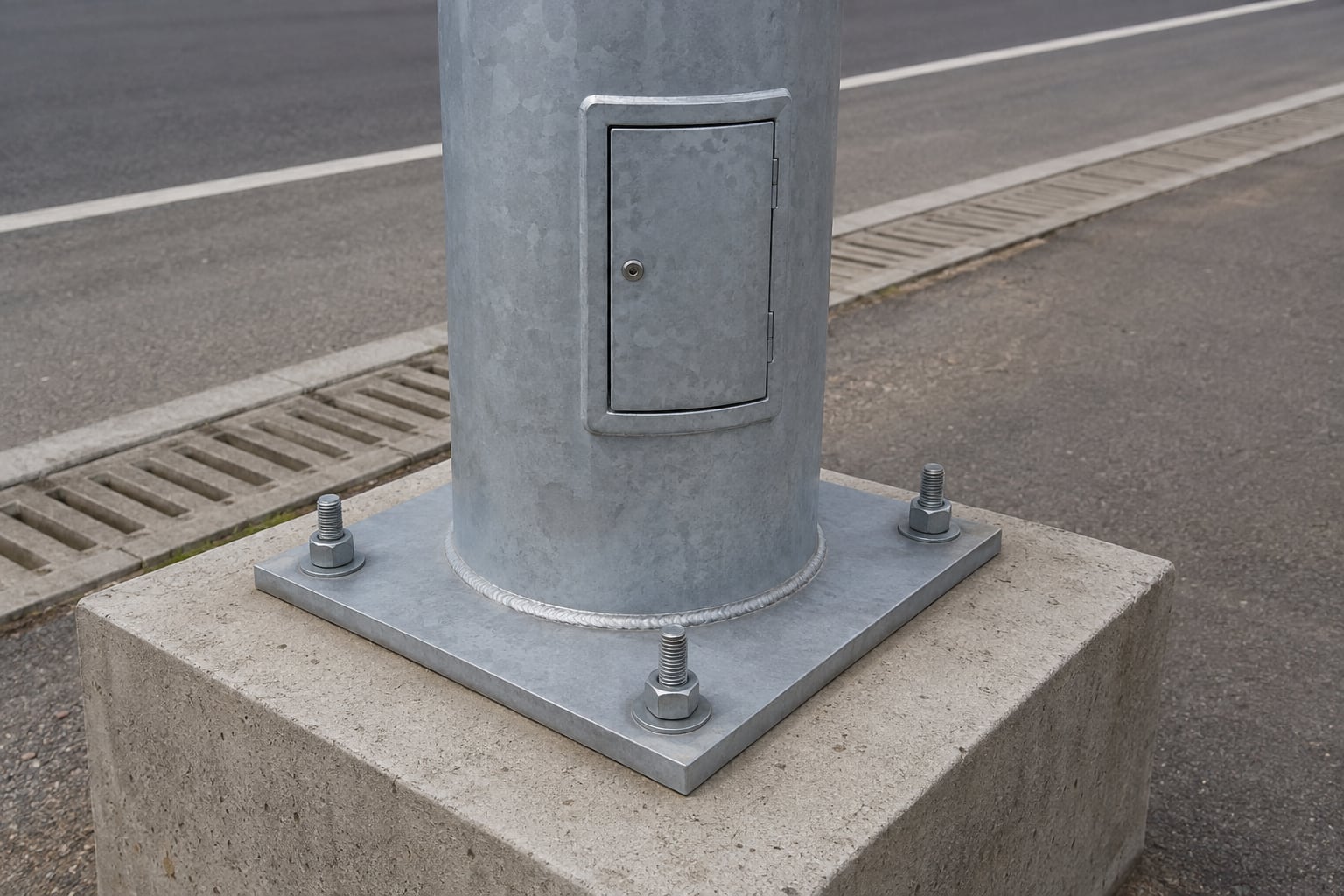
The base assembly transfers shaft actions into the anchor system and concrete support. Outside dimensions, thickness, bolt holes, cable opening, shaft weld and any stiffeners are coordinated with the calculated reactions. Sufficient access is required for nuts, washers, tools, cable entry and future inspection.
The approved detail should state the intended support condition, such as bearing arrangement, leveling method and grout if required. An unplanned gap beneath the base or a changed bolt circle can alter behavior. If an existing foundation must be reused, provide a verified survey of bolt size, spacing, projection and orientation together with an assessment of the foundation condition and capacity.
Foundation Reactions and Responsibility
The pole supplier can provide the actions at the base for the approved pole configuration and coordinate the supplied anchor assembly. The final concrete foundation depends on soil properties, groundwater, frost, slope, fill conditions, drainage, nearby utilities, concrete and reinforcement rules, and local civil practice. A qualified project engineer should design or verify it using site-specific information.
Reference sketches are useful for coordination but should not be treated as universal foundation designs. Highway shoulders, median barriers, bridge decks and retaining structures can impose tight spatial limits. Early exchange of base reactions and permitted foundation geometry reduces late changes to the pole or civil works.
Access Door and Reinforcement
The access opening provides entry to terminal blocks, protective devices, cable joints or other agreed electrical equipment. Because the opening removes shaft material near a highly loaded region, its size, corner radius, frame, reinforcement and position form part of the structural detail. The cover should fit securely and use a fastening method suitable for the project environment.
Door orientation should support safe maintenance and avoid live traffic where practical. Internal features can include an earthing lug, equipment rail and cable protection. The buyer should define equipment dimensions, wiring responsibilities and ingress expectations so the compartment is large enough without creating an unnecessarily large opening.
Cable Routing and Earthing
The foundation conduit, base opening, internal cable path and arm outlet should form a continuous route with protected edges and workable pulling space. Slip joints and detachable arms require enough allowance to route cables without crushing, sharp bends or abrasion. Cable length and termination method should match the actual assembly sequence.
Earthing and bonding provisions depend on the electrical design and local rules. An internal lug can be included when specified, but the complete system—including conductors, connection method and testing—remains part of project electrical coordination. The pole drawing should show the mechanical provision clearly rather than assuming the installer will drill the galvanized shaft.
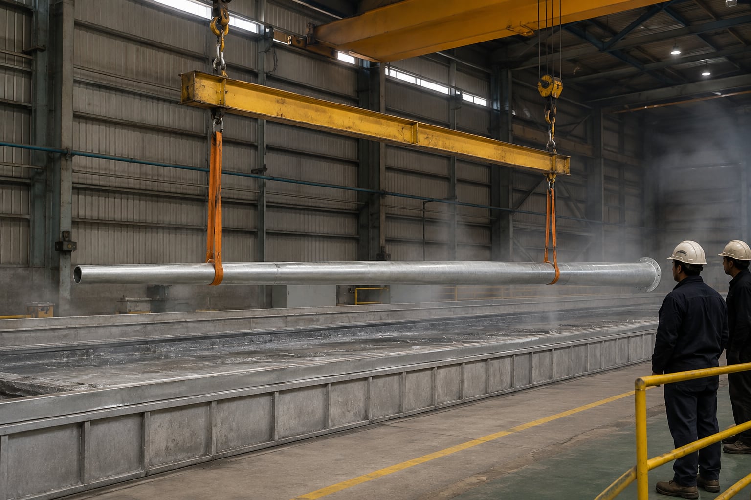
Hot-Dip Galvanizing Scope
Hot-dip galvanizing provides a bonded zinc coating to prepared steel and is commonly specified for highway poles. Hollow components need access for cleaning solutions and molten zinc so internal and external surfaces can be processed. Coating acceptance should reference the agreed galvanizing standard, material category, measurement method and permitted repair procedure.
Appearance can vary with steel chemistry, section thickness and cooling. Functional acceptance should follow the specified standard rather than a requirement for perfectly uniform color. Threaded areas, slip-joint surfaces and mating interfaces may need controlled finishing so the product remains assembleable after coating.
Venting and Drainage for Galvanizing
Closed cavities are unsafe and can prevent proper processing. Vent and drain openings should be designed before fabrication so air, liquids and zinc can move freely. Their size and location depend on the component geometry and galvanizer's handling method. Overlapping plates, sealed stiffeners and arm connections deserve particular attention.
The same detailing should avoid water traps after installation. Drainage paths must remain functional without creating exposed sharp edges or uncontrolled openings for pests and debris. Joint and cap arrangements should be reviewed together with the coating process and final installed orientation.
Optional Color Coating
A compatible organic color layer over galvanizing may be specified for appearance or additional barrier protection. The full system should define preparation of the zinc surface, pretreatment, coating material, color, thickness, curing or application controls, adhesion requirements and repair method. Simply applying paint to an unprepared galvanized surface is not an equivalent process.
Coastal salt, deicing chemicals, industrial contaminants, ultraviolet exposure and expected maintenance affect the selection. No fixed service life applies to every environment. For salt-exposed routes, review the dedicated coastal road duplex-coated lighting pole and the port access road lighting guide.
Fabrication Drawings and Hold Points
The shop drawing converts the order into controlled dimensions. It should identify the height reference, section lengths, shaft geometry, material and thickness, seam, door, arm, luminaire interface, base plate, anchors, cable openings, coating and assembly marks. Revision status and approval responsibility should be visible.
Project hold points can be placed before material cutting, before galvanizing, at trial assembly, during final inspection or before packing. The appropriate plan depends on specification and risk. Approval should occur early enough to avoid treating finished steel as the place to resolve photometric or civil-interface questions.
Dimensional and Visual Inspection
Inspection can include material identity, plate thickness, shaft length, dimensions across flats, taper, straightness, twist, hole pattern, base geometry, door position, arm interface and section matching. Weld appearance and specified nondestructive examination are recorded according to the agreed quality plan.
After coating, visible condition, drainage, coating measurements and relevant repaired areas can be reviewed. Inspection records should identify the order or item so documents remain traceable after packing. Acceptance criteria should come from the purchase specification and referenced standards, not be invented after production.
Coating and Galvanizing Records
The agreed document package may include coating measurement records, visual inspection results, repair notes and processor documentation. The buyer should specify required report formats and witness points during tendering. A request made after shipment may be difficult to reconstruct if it was not part of the order.
Records should correspond to the supplied items or production lot. This does not mean every project needs the same paperwork. Routine road work, authority tenders and third-party inspected contracts can have different submittal requirements, so the commercial offer should state what is included.
Trial Assembly and Interface Checks
Where required, sectional profiles can be checked for fit and engagement before coating. Arm connections, flange patterns, anchor templates and access covers can also be verified. Trial assembly is particularly useful when components are supplied from multiple parties or the pole must accept a buyer-nominated luminaire.
The check should focus on measurable interfaces rather than a cosmetic mock-up. Orientation marks, joint engagement, bolt access and cable routing matter at site. Any trial fit must be separated without damaging contact surfaces, then protected and identified for packing.
Packing for Long Components
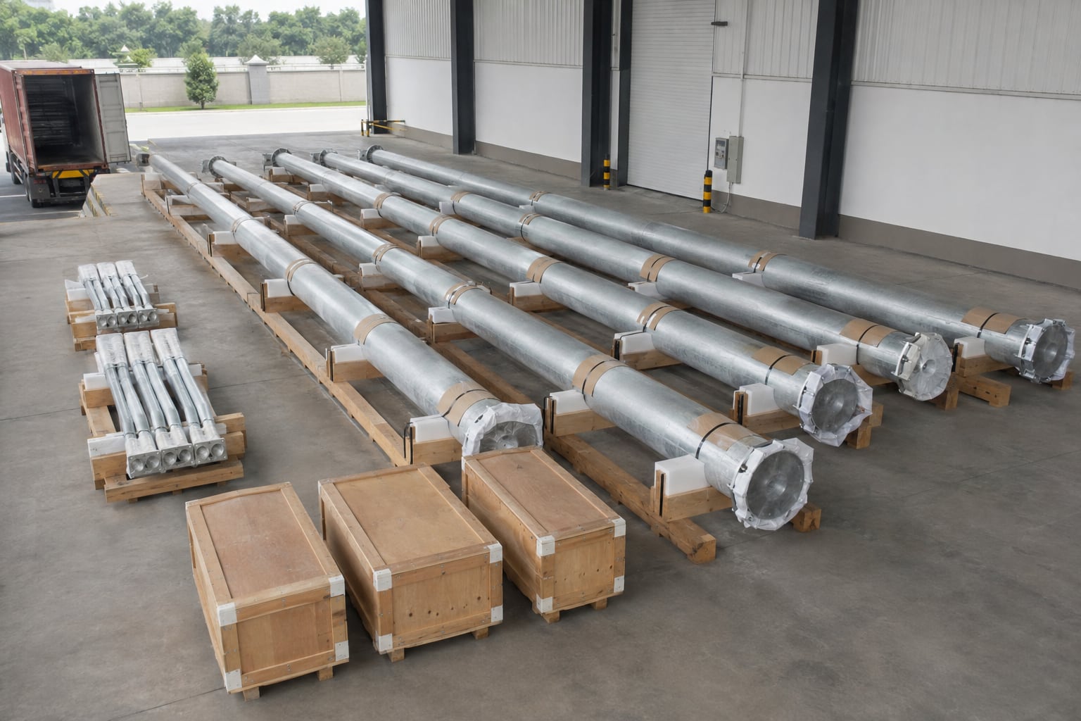
Long tapered shafts need supports placed to limit point loading, movement and coating abrasion. Contact materials should be compatible with the finish and suitable for expected storage conditions. Base plates, arms and protruding features require protection from impact. Loose hardware should be counted, labeled and packed in identified cases.
Bundles should remain stable through lifting and road movement, while preserving safe access for unloading. A packing list linked to item marks helps site teams match shaft sections, arms and anchors. The sequence can be planned so the first erection items are not buried beneath later-stage components.
Container and Inland Transport Planning
The shipping decision should consider actual section length, bundle dimensions and weight, not only nominal pole height. Standard container limits, open-top or flat-rack availability, break-bulk options, port handling and destination trucking can affect the most practical segmentation. Route restrictions may include turning radius, overhead clearance, escorts and delivery-hour limits.
Transport planning belongs near the start of the project because it can influence section joints and packing design. Jieyao can review packing efficiency using the intended quantity and destination, but carriers and local logistics providers must confirm route and equipment availability.
Lifting and Erection Planning
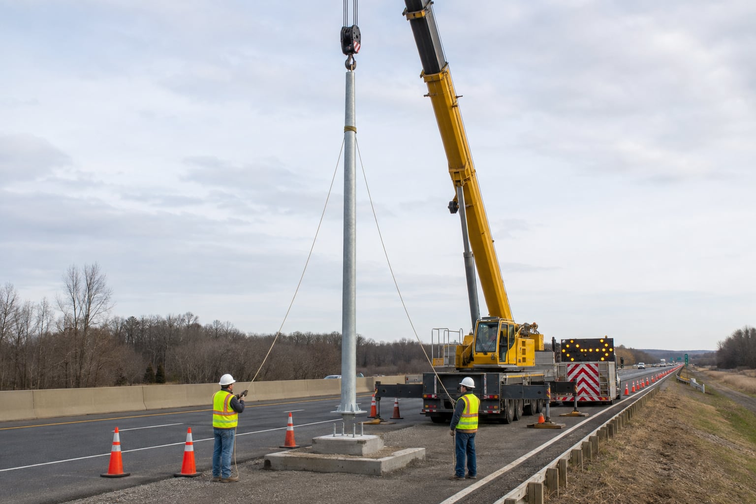
A 15m pole requires a planned lift using suitable equipment, competent personnel, controlled exclusion zones and the approved installation sequence. Lift points and slings should prevent uncontrolled rotation, local damage and coating abrasion. Tag lines may help orientation when site conditions permit. Workers should not stand beneath suspended components.
Sectional poles are assembled using the specified joint procedure before or during erection. The arm and luminaire may be installed at ground level or after the shaft is vertical depending on weight, access and lift plan. The selected method must remain consistent with equipment ratings, road closure arrangements and the structural details.
Installation and Alignment
Before lifting, the team should verify the foundation, anchor pattern, bolt projection, conduit position and concrete readiness. Nuts and washers must match the approved detail. During erection, the shaft is oriented so the door and arm face the correct directions. Plumb is checked using an appropriate method after the base connection is brought to its specified condition.
Cables should be protected while the shaft is moved and connected. Final checks include joint engagement, fastener condition, cover fit, arm security, luminaire alignment, earthing provisions and coating damage. Any repair should use the agreed method; unreviewed site welding or drilling can affect both structure and corrosion protection.
Maintenance Access
Roadside maintenance affects pole placement and component selection. The access door should be reachable without exposing workers to unnecessary traffic, and the luminaire should be serviceable with the planned vehicle or access method. Barriers, slopes, drainage channels and landscaping can make an apparently clear location difficult after construction.
Asset records should retain the approved luminaire and accessory load basis. Future signs, cameras or communication equipment should be reviewed before installation because added exposed area and eccentricity can change demand. Periodic inspection should follow the owner's environment, authority requirements and observed condition.
Compare Quotations on the Same Basis
A low quoted weight or a single wall-thickness value does not establish equivalence. Compare height reference, shaft geometry, steel grade, wall schedule, joint type, arm reach, luminaire load, wind basis, door reinforcement, base and anchors, galvanizing standard, records, packing and included accessories. Check whether civil foundation design, structural calculations or third-party inspection are included or excluded.
Resolve deviations in writing before purchase. A clear comparison reduces the chance that a cheaper offer omits anchors, uses a different wind definition or assumes a smaller fixture. If a lower mounting position is suitable, compare the published 12m highway lighting pole. For conventional road layouts, the 10m single-arm pole and 10m double-arm pole cover distinct shorter-height intents.
A complete commercial comparison should also state delivery point, unloading responsibility, included spare hardware, drawing turnaround and inspection timing. These details do not change keyword wording on a specification sheet, but they strongly influence whether the selected 15 meter street light pole package can move smoothly from approval to site erection.
RFQ Input Checklist
Define the road and quantity.Provide project location, road type, pole positions, roadside or median use, required quantity and delivery schedule.
Confirm the 15m reference.State whether it means shaft length, luminaire mounting height or installed overall height including bracket rise.
Attach the lighting arrangement.Send pole spacing, arm direction, outreach, rise, luminaire model, mass, EPA, mounting opening and tilt.
State structural criteria.Name the governing standard, wind definition, exposure, topography and any bridge, fatigue or authority requirement.
Define the civil interface.Provide permitted base size, new or existing foundation status, anchor constraints, conduit route and responsibility split.
Specify protection and appearance.Identify galvanizing standard, environment, optional color system, inspection, documentation and packing needs.
Related Pole Options
The correct product family follows function, not simply the tallest available pole. A shorter conventional pole can be more economical where the lighting design supports closer spacing. A fixed-arm 15m pole differs from a lowering high mast, and a highway lighting pole differs from a traffic-signal support carrying mast arms and signal loads.
Jieyao can review a project schedule containing several heights and arm types so interfaces remain consistent. Shared considerations may include luminaire tenons, door hardware, anchor templates, finishes and item marking, while each shaft retains its own structural configuration.
Frequently Asked Questions
What does 15m mean?
It must be defined as shaft length, luminaire mounting height or overall installed height on the drawing.
Is a 15m pole a high mast?
Not necessarily. A fixed-arm roadway pole is different from a multi-luminaire lowering high-mast system.
Can the shaft be one piece?
Possibly, if fabrication, galvanizing, transport, route access and erection equipment can handle the length.
Can it be supplied in sections?
Yes. The joint and section lengths must be engineered and shown on the approved drawing.
Are single and double arms available?
Yes. Arm geometry is matched to the road layout, luminaire and structural load basis.
What wind speed can it resist?
Capacity is project-specific and depends on the code, exposure, pole geometry, arms, fixtures and accessories.
What luminaire data is needed?
Provide mass, dimensions, EPA, mounting opening, insertion depth, tilt and center-of-gravity information.
Is the foundation included?
Pole reactions and anchors can be coordinated; final concrete design needs local soil and civil information.
Is the pole galvanized inside?
Hollow components are detailed for hot-dip galvanizing with suitable vent and drain paths.
Can a color finish be added?
Yes. A compatible coating system over prepared galvanizing can be specified by color and environment.
Are drawings supplied?
Project drawings are prepared for review before production; the agreed record package is listed in the offer.
What should I send for a quotation?
Send height reference, quantity, road layout, fixture data, wind basis, arm, finish, destination and schedule.
Request a 15m Highway Pole Proposal
Send your road cross-section, pole schedule, 15m height reference, arm layout, luminaire data, governing wind criteria, coating requirement, delivery destination and required documents. Jieyao will review the interfaces and prepare a project-specific configuration for quotation.
Contact Jieyao Lighting