

A clear guide for consultants, contractors and purchasing teams who need to define wind speed, exposure, topography, luminaire effective projected area, headframe geometry, foundation reactions and other inputs before a high-mast lighting system can be designed.
A high-mast lighting structure is a tall, slender system carrying luminaires, brackets, cables and sometimes a raising-and-lowering carriage. Wind acting on each exposed component creates shear, bending moment and, when loads are eccentric, torsion. The effects change with height, site exposure, equipment geometry and the structural code used for the project. A statement such as “suitable for 160 km/h wind” is therefore incomplete unless the speed definition, exposure assumptions, accessory arrangement and design standard are also stated.
Procurement teams should treat wind capacity as the outcome of a coordinated design, not a standalone product label. The supplier needs enough information to calculate the approved mast configuration and its base reactions. The local civil engineer then uses those reactions with soil and site information to design or verify the foundation. This guide explains the information flow without replacing project-specific engineering.
The governing standard defines how wind data is converted into design pressure and how loads, gust effects, importance, terrain, topography, dynamic behavior and resistance factors are treated. Different standards may express nominal wind speed differently and may use different averaging periods, recurrence intervals or load combinations. A number taken from a weather map under one standard cannot safely be inserted into calculations prepared under another without a documented conversion.
The RFQ should identify the required code edition, project authority and any supplementary specifications. If the tender only provides a design wind speed, the supplier should list assumptions for review rather than silently selecting an exposure or importance level. Final production drawings should state the approved design basis so the mast, anchors and foundation reaction schedule can be checked against the same criteria.
Wind-speed definitions can differ by averaging time, return period, height above ground and whether the value already includes a gust treatment. These differences materially affect calculated pressure. A consultant should provide the code-defined basic wind speed or a site-specific value in the exact form required by that code. Avoid mixing a three-second gust speed with a mean wind method or treating regional meteorological data as a finished structural design value.
A high mast in an open coastal field, airport, desert or highway embankment can experience a different wind profile from the same-height mast within a dense urban district. Structural standards represent this difference through terrain or exposure categories. Open terrain generally allows higher wind velocities near the structure than areas protected by closely spaced buildings and trees. The classification should describe the surrounding fetch in relevant wind directions, not only the immediate plot.
Future development also deserves attention. A site that is currently shielded by temporary buildings or vegetation may become more exposed during the mast's service life. The design team should follow the governing code and authority practice when defining the exposure. The manufacturer should not downgrade the category merely because a product page shows a sheltered installation photograph.
Ridges, escarpments, isolated hills and steep embankments can accelerate wind above the surrounding terrain. High-mast towers are often placed on raised highway interchanges or open industrial sites where this effect may be important. The relevant topographic factor depends on geometry, position and the chosen standard. A simple site elevation does not show whether amplification applies.
Provide a site plan, levels and terrain description when the mast is near a slope or crest. The structural consultant should determine the code input. If that decision is pending during budgeting, the quotation should clearly identify the provisional assumption and prevent manufacture until the approved value is issued.
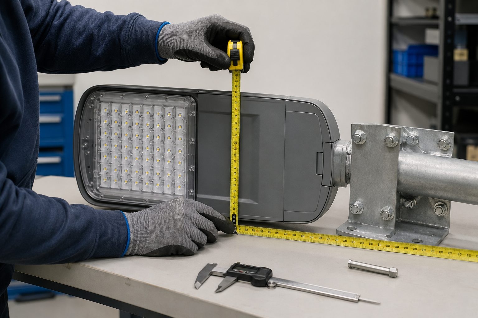
Effective projected area, commonly shortened to EPA, is a practical way to represent the wind effect of an accessory. It combines the projected area normal to the wind with an aerodynamic force or drag coefficient. For a luminaire, the relevant value may vary with orientation because the front, side and inclined profiles are different. EPA is not the physical surface area, the top-view area or the fixture weight.
Manufacturers may publish EPA for defined mounting angles or reference axes. The high-mast designer needs values that are compatible with the project's design method. Where reliable EPA data is unavailable, the dimensions and shape information must be assessed using the governing standard. Never estimate all luminaires from the carton size or use the smallest visible face for every wind direction.
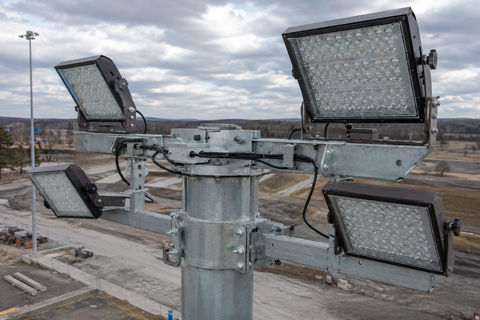
The luminaire EPA is only part of the total wind-exposed system. The calculation also considers the headframe or carriage, brackets, mounting plates, cables, junction enclosures, shaft and any approved cameras, signs, antennas or lightning-protection components. Items near the top of the mast have a large lever arm, so a modest additional area can materially change the base moment.
Equipment can also shield or interact with adjacent components. The method used to combine these effects should follow the design standard and approved structural model. A tender should show the quantity, position, orientation and EPA basis of every accessory rather than providing one untraceable total.
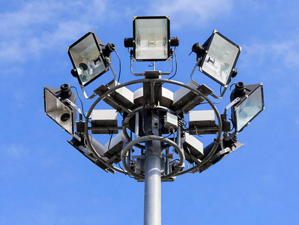
High-mast floodlights are often aimed in different azimuths and tilt angles around a circular or multi-sided carriage. Wind can approach from any direction, and the governing arrangement may not be the visually widest elevation. The designer should evaluate relevant wind directions and account for eccentricity from the mast centerline. Symmetrical-looking layouts can still create torsion when fixture sizes, aiming or brackets differ.
When the photometric design changes, the structural accessory schedule should be reviewed. Replacing a luminaire with a heavier housing or increasing tilt may affect weight, EPA, center of gravity and cable arrangement. Procurement substitutions therefore require both optical and structural approval.
A fixed headframe and a lowering carriage transfer loads differently through their connections and operating components. The approved drawing should define arm lengths, mounting points, luminaire count, carriage diameter, cable routing and any latching arrangement. Longer arms increase moment and may introduce torsion even when fixture EPA is unchanged.
For a raising-and-lowering system, structural coordination also includes suspension ropes, power cable, guides, winch and carriage stability. These components need their own inspection and operating requirements. Jieyao's 30m raising-and-lowering high mast is configured around the approved head assembly and maintenance method rather than a universal fixture schedule.
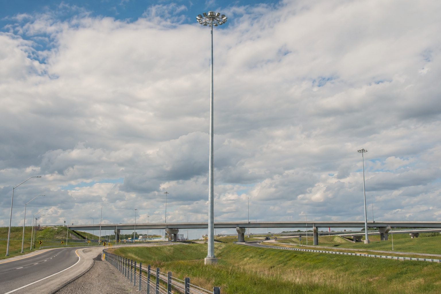
Wind pressure and the lever arm both influence the base action. Accessories mounted high above the foundation contribute more overturning moment than similar equipment close to the ground. The wind profile may also increase with height depending on the exposure model. This is why a 35m high-mast tower is not simply a longer version of a 20m system.
Preliminary selection can begin with product families such as a 20m high-mast lighting system or 35m high-mast tower, but the final shaft sections, wall schedule, joints, base and accessories follow project calculations. The reference height must also be defined: foundation level, mast top, carriage level and luminaire center are not always identical.
High masts are commonly fabricated as tapered polygonal steel sections. The number of sides, taper, steel grade, plate thickness and sectional arrangement influence stiffness, strength, fabrication and transport. The wall schedule is normally developed from structural demand and manufacturing limits, with attention to local stresses at joints, openings and connections.
A single thickness stated for the entire tower may not represent the final engineered design. Buyers should request a section schedule on the approved drawing and ensure that material documents correspond to the specified grades. Any change in accessory loading should be checked before plate is released for fabrication.
Long high masts are usually shipped in sections for transport. Tapered sections may use engineered slip joints with specified overlap and compatible profiles. The joint must transfer axial load, bending, shear and other code-required effects while maintaining alignment. Actual engagement can depend on geometry, tolerances, surface condition and controlled assembly procedure.
The erection documentation should define orientation marks, minimum or target engagement, pulling or jacking method where applicable, acceptable gaps and inspection records. Field crews should not force an incompatible section or drill unapproved holes. Packing plans should keep matched sections identifiable from factory trial assembly through delivery.
The access opening near the mast base is a structural discontinuity in a highly loaded region. Its dimensions, corner geometry, frame, door and reinforcement must be included in the design. The opening also needs sufficient space for winch, electrical and inspection access without weakening the shaft through uncontrolled field modification.
Door orientation affects accessibility and may influence wind-related local checks or internal equipment layout. The civil and electrical plans should coordinate the opening with traffic, drainage and cable entries. Additional holes, brackets or cabinets should not be welded or cut onto a finished mast without engineering review.
Tall slender structures can respond dynamically to wind. Along-wind gust response, cross-wind vortex effects and accessory-induced behavior may require checks under the governing standard or authority specification. The importance of these effects depends on mast frequency, damping, shape, height, wind climate and head assembly. A static base-strength check alone may not address every required limit state.
Excessive vibration can affect fatigue-sensitive details, luminaires, cables and lowering equipment even when gross strength remains adequate. The project engineer should identify required dynamic or fatigue provisions. If mitigation is needed, it must be designed for the actual mast rather than added as an unverified field modification.
Wind usually governs many high-mast checks, but permanent and operational loads remain essential. The structural model includes shaft self-weight, carriage, luminaires, cables, winch equipment and other supported items. Raising or lowering can introduce operational effects and temporary configurations that differ from the normal locked position.
The supplier should know the luminaire mass and center of gravity as well as EPA. Installation and maintenance plans should define whether the carriage is latched, suspended or temporarily supported during each operation. Using a heavier substitute fixture without review can affect both the wind response and lowering-system capacity.
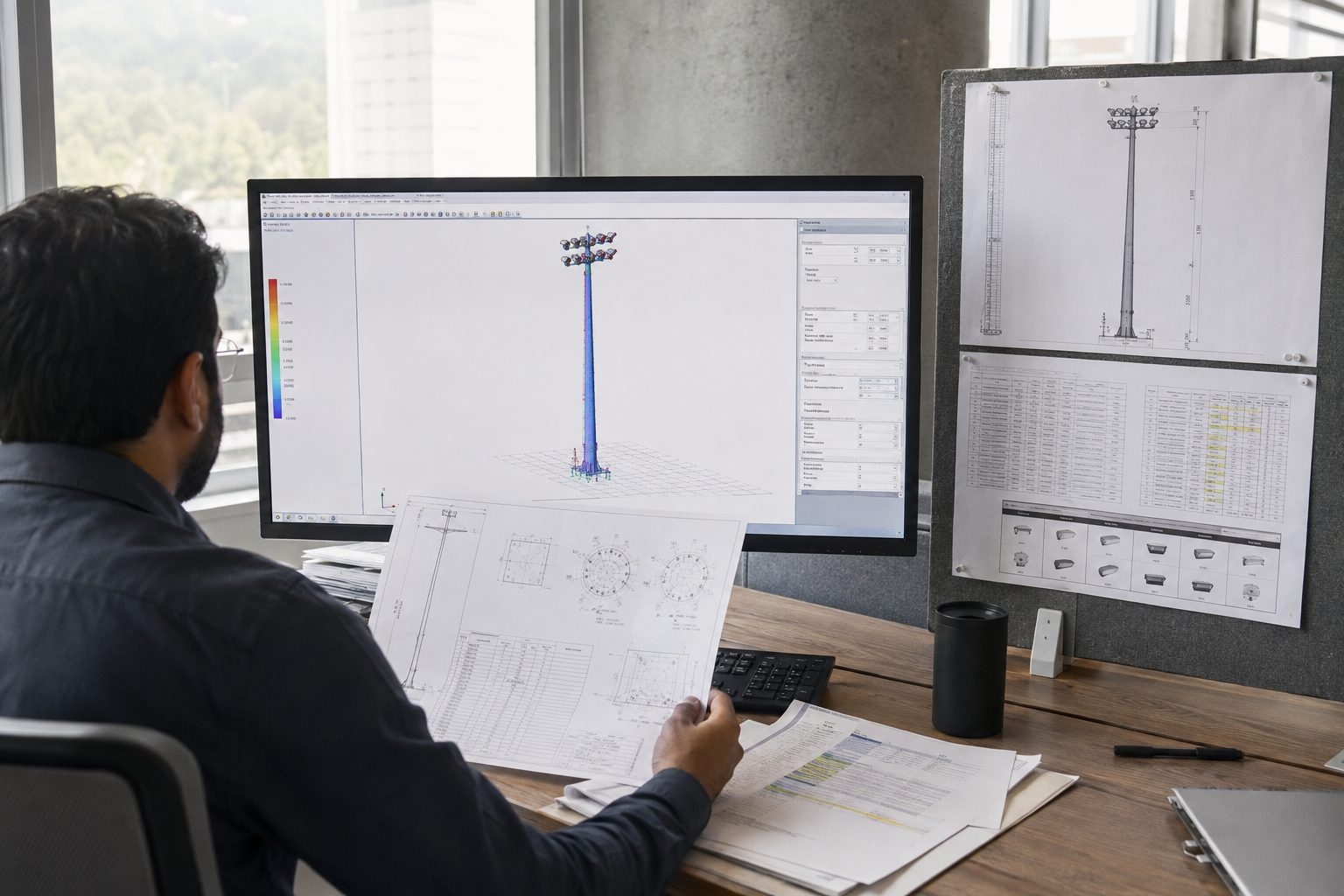
The structural analysis converts the approved wind inputs and component geometry into effects throughout the mast. At the base, the designer reports a coordinated set of reactions such as axial force, shear, bending moment and torsion for the specified load combinations. Civil design should use the reaction set and definitions supplied for the exact approved configuration.
A single “foundation load” is rarely enough. Reactions can change with wind direction and accessory arrangement. The schedule should state units, coordinate axes, service or ultimate basis as applicable, and whether values are simultaneous. This prevents the foundation engineer from combining unrelated maxima or applying an incorrect factor twice.
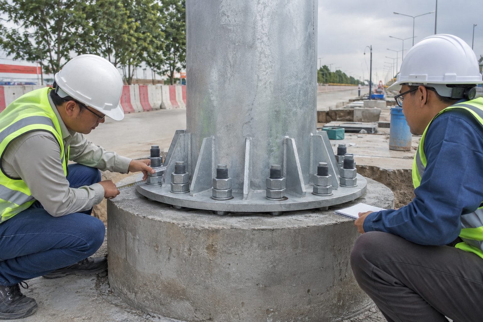
The base plate, stiffeners, welds, anchor circle, anchor rods, nuts and washers form one load path between the mast and concrete. Their design depends on the approved reactions, geometry, materials and code provisions. A larger bolt diameter alone does not solve an unsuitable bolt circle or inadequate base plate.
Anchor projection, thread length, template position, conduit opening, leveling arrangement and grout detail must be coordinated before concrete placement. The supplied anchor assembly should match the approved mast drawing. Substituting anchors based only on visible dimensions can change material strength, embedment behavior and installation tolerances.
The mast supplier can provide base reactions and anchor information, but the final foundation depends on soil strength, stiffness, groundwater, frost, drainage, seismic criteria, nearby slopes, utilities and local construction practice. A foundation detail from another project is not automatically suitable even when the mast height appears similar.
A qualified local civil or geotechnical engineer should verify bearing, sliding, overturning, uplift, settlement, concrete, reinforcement and anchor development according to the governing requirements. The foundation also needs practical conduit routes, drainage and access. Early exchange between structural, civil and electrical teams reduces costly field changes.
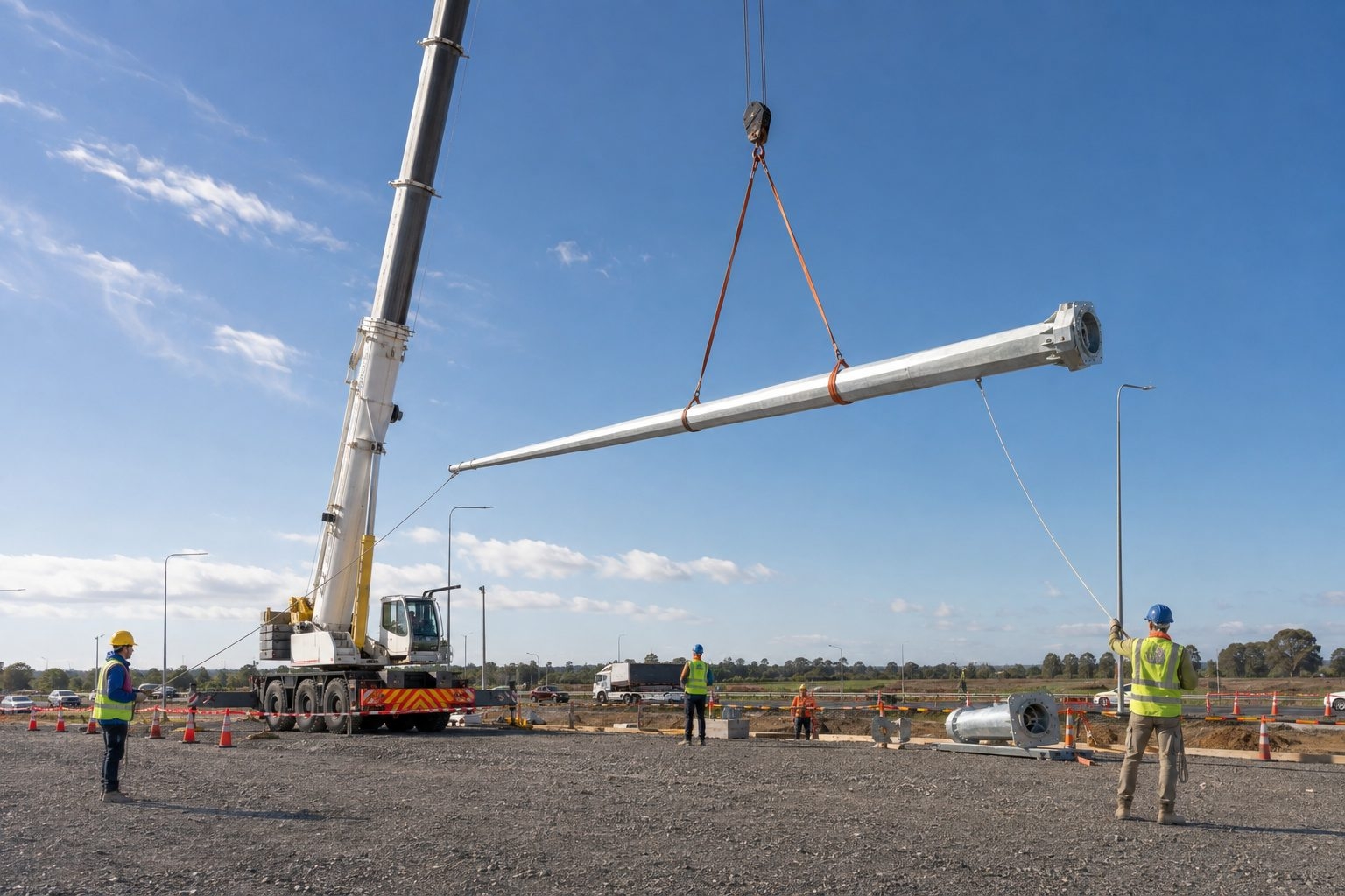
Mast sections can be vulnerable during storage, horizontal assembly and lifting. The permanent design assumes a completed configuration, while temporary support points and crane rigging create different forces. Wind limits for lifting should be defined by the erection plan, crane requirements and site safety procedures rather than inferred from the mast's design wind speed.
Sections should be supported to avoid local denting and uncontrolled rolling. The lift plan should identify weights, centers of gravity, approved lifting points, sling protection, tag lines, exclusion zones and weather monitoring. No person should work below a suspended section. If wind or visibility exceeds the permitted conditions, the lift should stop.
Hot-dip galvanizing is widely used for steel high masts, but coating selection should match the environment and project standard. Drain and vent holes required for galvanizing must be coordinated with structural details. Crevices, trapped water, dissimilar metals and coating damage around connections can shorten service life if not addressed.
Surface condition also affects slip-joint assembly and hardware installation. Any repair procedure should be compatible with the specified coating standard. Optional paint over galvanizing may provide color or an additional barrier, but preparation and system compatibility need definition. Corrosion allowance or special protection should be determined by the project engineer rather than assumed from appearance.
Cameras, antennas, signs, banners, solar modules and communication boxes can add projected area, weight and eccentricity. Because they may be placed high on the mast, even compact accessories can alter bending or torsion. Cable attachments and field-drilled holes can introduce additional problems.
The owner should maintain an approved accessory schedule and require structural review before additions or substitutions. If future equipment is anticipated, provide its envelope during the original design. Reserving capacity should be explicit and documented; it should not be assumed simply because the tower looks substantial.
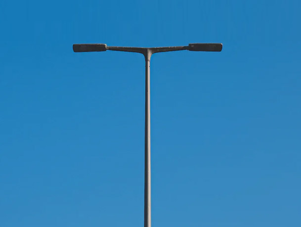
A 12m highway street-light pole normally carries fewer luminaires at a lower height, while a high mast consolidates multiple floodlights on a much taller structure. Both are wind-sensitive, but the high mast typically creates larger overturning demand, sectional joints and additional dynamic and maintenance-system considerations.
The correct choice is made from photometric coverage, site constraints, wind, foundations and service access. The guide to street poles versus high masts at highway interchanges explains how the mounting strategies can also be combined in one project.
| Input Group | Information to Provide | Why It Matters |
|---|---|---|
| Site and code | Location, authority, structural standard and edition | Defines the design framework and review basis |
| Wind | Speed definition, exposure or terrain, topography and importance | Controls pressure and reliability assumptions |
| Geometry | Mast height reference, headframe, carriage and section limits | Sets lever arms, stiffness and transport arrangement |
| Luminaires | Quantity, weight, EPA, dimensions, aiming and brackets | Defines top load, eccentricity and torsion |
| Accessories | Cameras, signs, cables, boxes, antennas and future allowance | Prevents unreviewed load additions |
| Civil | Soil report, levels, groundwater, utilities and foundation constraints | Connects mast reactions to a site-specific foundation |
| Operation | Fixed or lowering head, maintenance method and erection access | Coordinates equipment, temporary conditions and safe servicing |
| Delivery | Section-length limits, route, packing and erection schedule | Aligns fabrication joints with practical logistics |
A useful submittal includes the design criteria, general arrangement, mast sections, steel grades, wall schedule, slip joints, openings, headframe or carriage, fixture interfaces, base plate, anchors and corrosion protection. The accessory schedule should match the photometric design. Base reactions and coordinate definitions should match the exact configuration submitted for approval.
Project documentation may also include material records, dimensional checks, weld inspection scope, galvanizing inspection, trial assembly, lowering-system tests and packing lists as agreed in the contract. The submittal should distinguish routine factory controls from project-specific certification or third-party inspection. Final manufacture follows approved drawings and revisions.
A speed without code, definition, exposure and topography does not form a complete design basis.
Physical projected area and effective projected area are not necessarily the same.
Fixture tilt, azimuth, bracket length and eccentricity can change the governing load.
Reactions, soil, groundwater and site geometry must be verified for the actual location.
A replacement luminaire can change weight, EPA, aiming and lowering-system demand.
Accessories require review unless explicit reserved capacity was included and documented.
Confirm the code, wind definition, exposure, topography, importance and authority requirements.
Coordinate luminaire models, EPA, weight, aiming, brackets, carriage and every accessory.
Calculate sections, joints, openings, dynamic checks, base plate, anchors and reactions.
Give the approved reactions and anchor arrangement to the local civil engineer.
Verify section lengths, transport, assembly area, lifting conditions and safe maintenance access.
Recheck structural interfaces whenever luminaires, accessories, height or site criteria change.
EPA means effective projected area, an input used to represent an accessory's wind effect.
No. The designer also needs EPA, dimensions, orientation and mounting geometry.
No. The code, speed definition, exposure, topography and equipment vary by project.
Not usually. The complete design must include the frame, brackets and other accessories.
A local civil engineer verifies it using mast reactions and site soil information.
Only after optical, structural and lowering-system compatibility is reviewed.
Tilt can change projected area, drag, eccentricity and the governing wind direction.
They are checked as required by the governing standard and project specification.
Only after the reactions, anchors, soil and local requirements are verified.
Send the site, code, wind basis, height, luminaire data, accessories and civil constraints.
Send Jieyao the site location, governing standard, wind definition, exposure, topography, mast height, luminaire schedule, EPA data, aiming, accessories, lowering preference, soil information and delivery limits. We can organize a coordinated high-mast configuration, technical drawing and foundation reaction package for project review. Final structural and performance details follow approved inputs and drawings.
Send Wind and Luminaire RequirementsContact Us
Get a custom lighting solution and quotation for your project. Outdoor lighting manufacturer in Yangzhou, ChinaAbout Jieyao LightingYangzhou Jieyao Lighting Equipment Co., Ltd. is an outdoor lighting manufacturer focused on solar street light systems and high mas... Do you have any questions or requests?
Email: jay@jieyaolighting.com

Click to Chat.
Im online now.