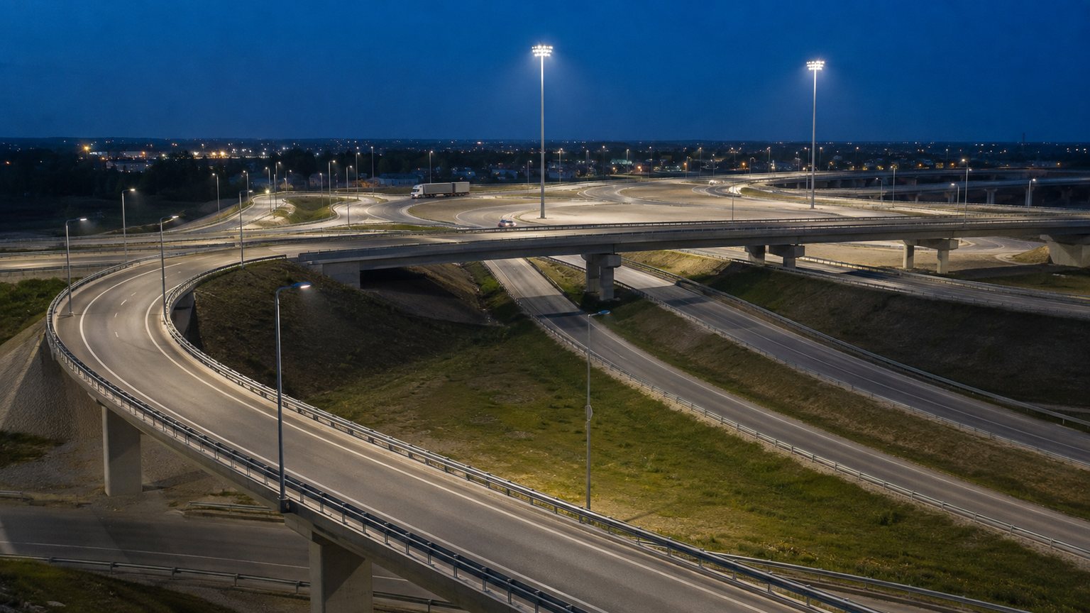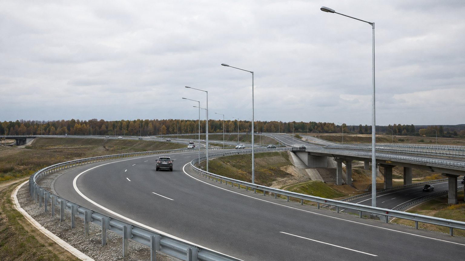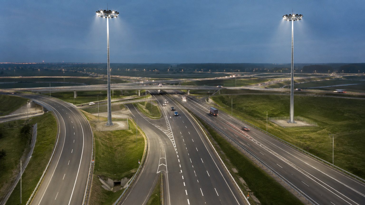


A practical comparison of 10–12m roadway poles, 20–40m high-mast towers and hybrid layouts for ramps, merge zones, toll approaches and large interchange centers. The right choice is made zone by zone from photometric, structural, civil, electrical and maintenance inputs.
This guide helps owners, consultants, contractors and purchasing teams compare the two common mounting strategies used in highway interchange lighting. Conventional street-light poles place roadway luminaires close to an individual ramp or carriageway. High-mast towers raise multiple floodlights above a much larger operational zone. Both systems can produce effective results when the optics, mounting geometry and site conditions are coordinated. Neither system is automatically superior for every interchange.
Start with the road geometry and the required lighting criteria, not a preferred catalogue item. Divide the interchange into decision zones, run a preliminary photometric study, identify structural and civil constraints, then compare installation and maintenance access. The final design should follow the governing road-lighting standard and the authority's requirements. Pole dimensions, foundations and electrical architecture must be based on approved project information rather than copied from a generic detail.
An interchange contains several visual tasks. A driver approaching a decision point needs to read signs, recognize lane boundaries and detect vehicles entering from a ramp. At a broad central area, the designer may need useful light over several elevated and ground-level surfaces. Near a bridge barrier, toll structure or residential boundary, spill light and foundation space may govern the decision. These tasks occur at different heights, orientations and distances.
A uniform equipment schedule can simplify procurement, but forcing one mounting height across every zone may create excessive poles, poor aiming, difficult foundations or unnecessary glare. A better layout gives each pole a defined job. Roadway poles can trace curved ramps and provide directional continuity. High masts can cover open zones where many smaller poles would otherwise be required. A hybrid design coordinates the transition between them so drivers experience consistent guidance.
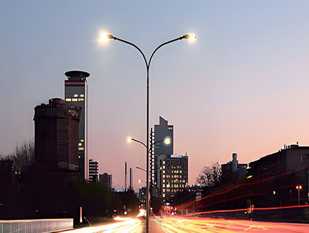
Roadway poles are well suited to linear sections where the target surface follows a clear edge: entrance and exit ramps, collector-distributor roads, bridge approaches, frontage roads and narrow medians. Their luminaires can use roadway distributions that send light along and across the pavement while limiting backlight. The repeated pole line also provides visual guidance through a curve, especially when spacing and setback remain consistent.
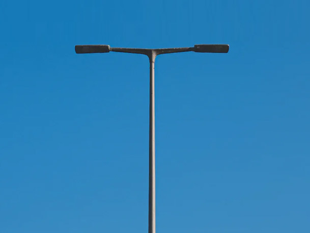
A 10m double-arm pole may serve a median or two adjacent directions, while a 12m highway light pole can support broader coverage on wide approaches. Shorter mounting is not automatically easier: more pole locations may mean more trenches, foundations and roadside conflict points. The photometric layout and civil plan should therefore be reviewed together.
Closely coordinated roadway optics can follow changing alignment and emphasize the lane path without lighting an unnecessarily large surrounding area.
Lower poles may fit controlled structural attachment zones and can be positioned around barriers, expansion joints and clearance envelopes.
Precise distributions and moderate mounting heights can support spill-light control near homes, sensitive land or adjacent facilities.
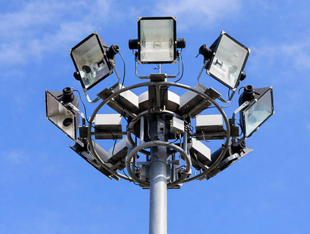
High-mast lighting is most useful where a small number of elevated lighting points can serve a broad, open and geometrically complex zone. Typical locations include large central interchange areas, multi-level merge zones, toll plazas, service compounds and expanses where frequent roadside foundations would interfere with barriers, drainage or vehicle recovery areas. A tower may carry a circular or multi-sided luminaire carriage with several floodlights selected for the required reach.
Mounting heights commonly fall within a project-defined range such as 20–40m, but the correct height depends on coverage, glare, wind, access and authority practice. Jieyao's 20m high-mast system, 30m raising-and-lowering high mast and 35m high-mast tower represent configurable starting points, not universal solutions. Final luminaire quantity, shaft sections, base plate and lowering equipment follow the approved project design.
Many effective interchange layouts combine high masts in the large central zone with roadway poles along ramps and approaches. The high masts provide broad ambient coverage over conflict areas, while the smaller poles maintain directional light where pavement curves, splits or passes behind structures. This avoids asking a distant high-mast floodlight to reach every shadowed ramp and avoids filling a large central field with many individual poles.
A hybrid scheme needs deliberate overlap. Too little overlap can create abrupt brightness changes at the transition. Too much can waste energy and increase glare. The photometric model should show the contribution of each luminaire group and allow circuits or controls to be evaluated separately. Equipment schedules should also distinguish poles, brackets, luminaires, control gear, cables, anchors and foundations so procurement teams do not assume that similar-looking locations use identical assemblies.
| Decision Factor | 10–12m Roadway Poles | 20–40m High-Mast Towers |
|---|---|---|
| Typical role | Linear ramps, road edges, medians and approaches | Broad interchange centers, plazas and large merge zones |
| Optical character | Directional roadway distribution close to the target | Wide-area floodlighting from a high mounting point |
| Number of locations | Usually more foundations and cable branches | Usually fewer but substantially larger foundations |
| Structural demand | Lower individual height and accessory load, still wind-critical | Large wind-exposed system with sectional shaft and head assembly |
| Maintenance | Bucket truck or access equipment at each pole | Lowering carriage can bring luminaires to ground level |
| Traffic interface | More roadside work locations | Fewer service points, but each point requires a planned work zone |
| Best constraint | Precise control near boundaries and curved pavement | Coverage over open, complex and hard-to-reach central areas |
This comparison is directional. Project geometry, standards, luminaire data and civil conditions can change the preferred solution.
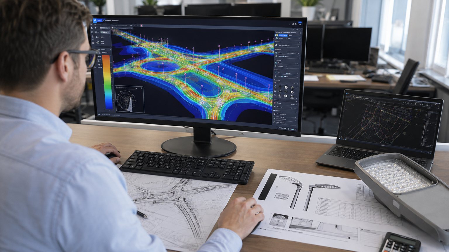
A reliable interchange lighting design uses a digital model of carriageways, ramps, barriers, bridges, signs and relevant surrounding areas. The lighting designer places candidate luminaires with verified photometric files, mounting heights, outreach, tilt and orientation. Calculation grids then evaluate the metrics required by the governing standard, which may include average luminance or illuminance, overall and longitudinal uniformity, threshold increment, edge lighting and vertical illumination.
Rules of thumb such as “spacing equals four times the height” cannot capture curves, elevation changes, asymmetrical optics or obstruction from a flyover. They may be useful for an early quantity estimate, but they should not release equipment for production. A design review should confirm the luminaire model and photometric file revision because a housing that looks similar can have a different lens, distribution and lumen package.
A high average value does not guarantee comfortable or useful visibility. Bright pools separated by dark gaps force the eye to adapt repeatedly and can make objects harder to recognize. Uniformity is particularly important near merge, diverge and weaving zones where drivers scan several directions. Longitudinal consistency also helps the driver understand the path ahead at speed.
Roadway poles can improve continuity along a ramp because their spacing follows the alignment. High masts can create broad overlapping fields, but poor aiming or excessive spacing may leave shadows beneath bridges and at grade-separated edges. The model should inspect individual conflict areas, not only a combined summary grid. Where the project uses adaptive dimming, the lowest operating scene should still meet the criteria assigned to that traffic condition.
Higher mounting can reduce some forms of source brightness in the driver's field of view, yet a high-mast luminaire aimed too far across the site may still cause disability or discomfort glare. Roadway luminaires with excessive tilt can expose bright optical surfaces to approaching traffic. Sign faces, wet pavement and reflective barriers can further influence visual conditions. Glare assessment therefore belongs in the photometric review, not as a generic statement about pole height.
Transitions also matter. Drivers moving from a brightly lit central interchange onto a lower-level ramp need a controlled change rather than a sudden drop. Near residential or environmentally sensitive boundaries, backlight and high-angle light should be limited through optic selection, aiming, shielding and location. A lower pole close to the pavement may sometimes provide better control; in another geometry, one carefully aimed high mast may reduce the number of sources visible from outside the site.
Raising the luminaire can widen its potential coverage, but it also changes intensity, aiming distance, structural load and maintenance method. Increasing spacing to reduce pole count may require more lumens or a different distribution and can weaken uniformity. Reducing spacing increases foundations, trenching and roadside hardware. The optimum is a coordinated system cost and performance decision rather than a height-only choice.
For roadway poles, define whether the stated 10m or 12m refers to nominal shaft height, mounting height or the height to the luminaire center. Bracket rise and road crossfall can create differences. For high masts, state the reference level, carriage position and head-frame arrangement. These definitions prevent errors when the civil drawing, pole schedule and photometric model are prepared by different parties.
A roadway luminaire typically uses a distribution designed to project along the travel direction and across a defined road width. High-mast floodlights may use several beam patterns around one head, each aimed at a separate zone. Wattage alone does not describe either result. The design team needs the photometric file, initial output, maintenance assumptions, color characteristics, surge protection and control compatibility.
The pole supplier also needs mechanical data: fixture weight, effective projected area, center of gravity, mounting opening, tenon size, bracket reach, tilt range and cable route. Multiple floodlights and their carriage create a substantial wind-exposed assembly at the top of a high mast. Cameras, signs, antennas or banners should not be added without review. For general roadway configurations, see the steel street-light pole range.
Energy comparison should be based on the complete designed layout and operating schedule, not simply fixture wattage. A high-mast scheme may use fewer locations but several powerful floodlights at each tower. A roadway-pole scheme may use more luminaires at lower individual output. The model should total connected load, predicted annual operating hours and any dimmed scenes that are permitted by the authority.
Useful controls can include astronomical time schedules, photocells, central monitoring, circuit-level switching and traffic-responsive dimming. The control architecture must preserve safe fallback behavior and should separate zones with different operating needs. Driver circuits, communication interfaces, surge protection and cabinet locations need coordination before procurement. Claimed energy savings should always identify the baseline, maintained light level and operating profile used in the calculation.
Highway sites are often exposed, elevated or located on embankments. A wind speed stated without its governing code, averaging period, return period, exposure category and topographic assumptions is incomplete. The structure must be checked using the applicable standard and the total effective projected area of luminaires, brackets, head frames and accessories. A numerical wind rating from an unrelated project should not be copied into a new tender.
Roadway-pole design considers shaft taper, steel grade, wall schedule, arm geometry, door opening, welds, base plate and anchors. High-mast design adds sectional joints, a larger luminaire assembly, internal lowering equipment and dynamic considerations appropriate to the code and authority. The supplier should receive the site wind basis and approved equipment loads early enough to develop a coordinated drawing and reaction schedule.
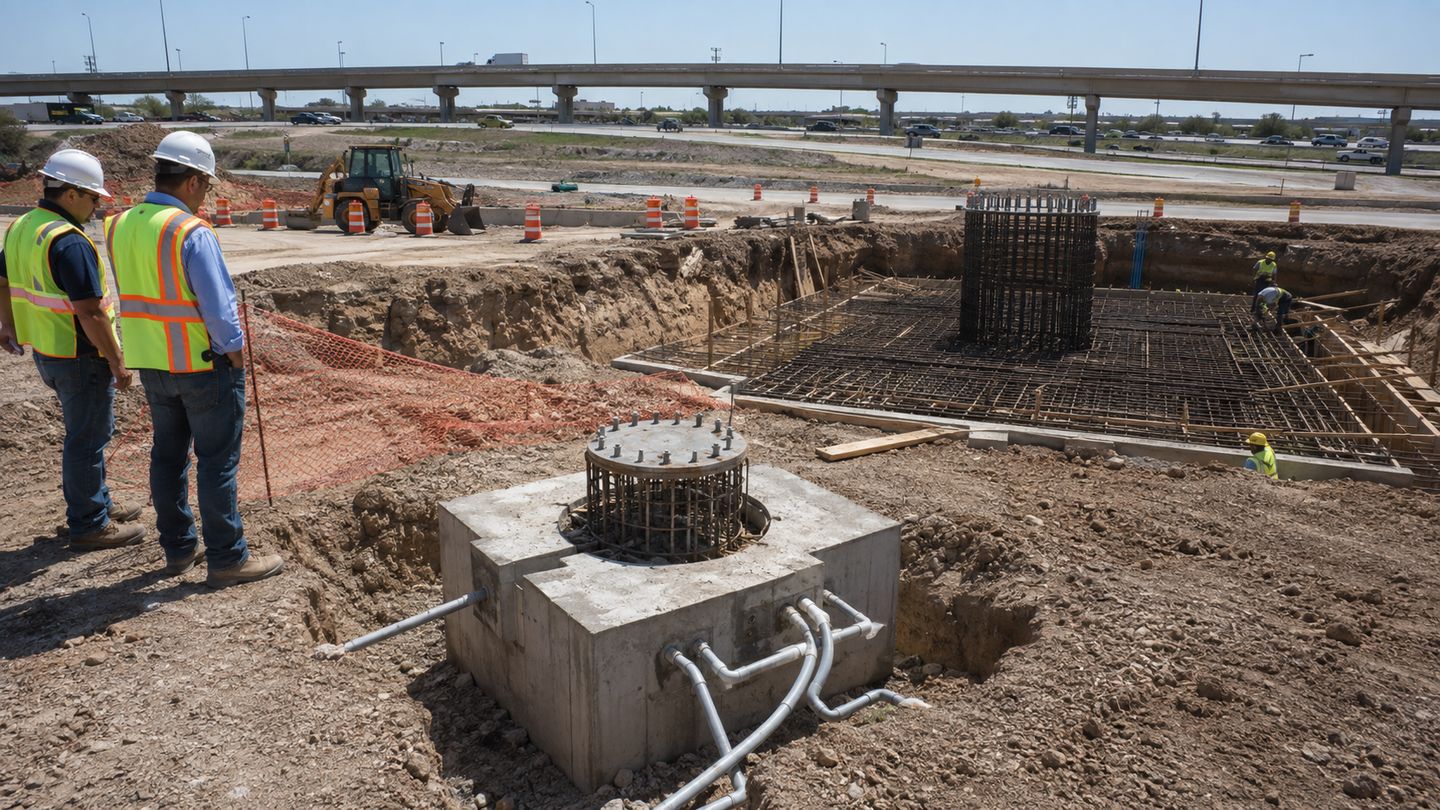
A roadway layout may require many relatively compact foundations distributed along ramps. A high-mast tower concentrates larger overturning, shear and axial reactions into fewer locations. The apparent advantage of a lower pole count can disappear if the preferred high-mast locations conflict with drainage channels, bridge foundations, buried utilities, unstable fill or restricted right-of-way. Conversely, one suitable central foundation may avoid extensive trenching and numerous roadside penetrations.
The pole supplier can provide base reactions and an anchor arrangement for the selected structure. A qualified local civil engineer should design or verify the concrete foundation using soil, groundwater, frost, slope, reinforcement, concrete and site constraints. The base plate, bolt circle, anchor grade, embedment, conduit entry and template should be approved before concrete placement. Reference drawings are coordination aids, not universal foundations.
Bridge decks and elevated ramps introduce attachment limits that may favor a specific mounting system. Designers must avoid prestressing ducts, reinforcement conflicts, waterproofing damage and unverified barrier connections. Vibration, fatigue provisions, turbulent wind and authority-specific breakaway or containment requirements may apply. A conventional ground-mounted base detail should not be transferred to a bridge without structural review.
Setback from the carriageway, clear-zone requirements, guardrails and maintenance access influence every pole location. The luminaire should not be positioned where the bridge structure blocks its light or where a service vehicle cannot stop safely. In some interchanges, high masts can be placed beyond the immediate roadside hazard zone. In others, terrain or access makes a sequence of barrier-integrated roadway poles more practical.
Numerous roadway poles can create long branch circuits with repeated joints and handholes. High masts may concentrate a larger electrical load at fewer points, but the cable route to each tower can still be long. The electrical design should calculate voltage drop, protective-device coordination, conductor size, earthing, surge protection and fault response for the selected layout.
Access doors, terminal blocks, isolators, feeder pillars and control cabinets must remain reachable without unsafe exposure to traffic. Conduits should be coordinated with anchor cages and drainage before foundations are cast. Where bridge expansion joints or separate earthing zones are involved, the authority's electrical details govern. Procurement documents should distinguish equipment supplied inside the pole from site cabling and external switchgear.
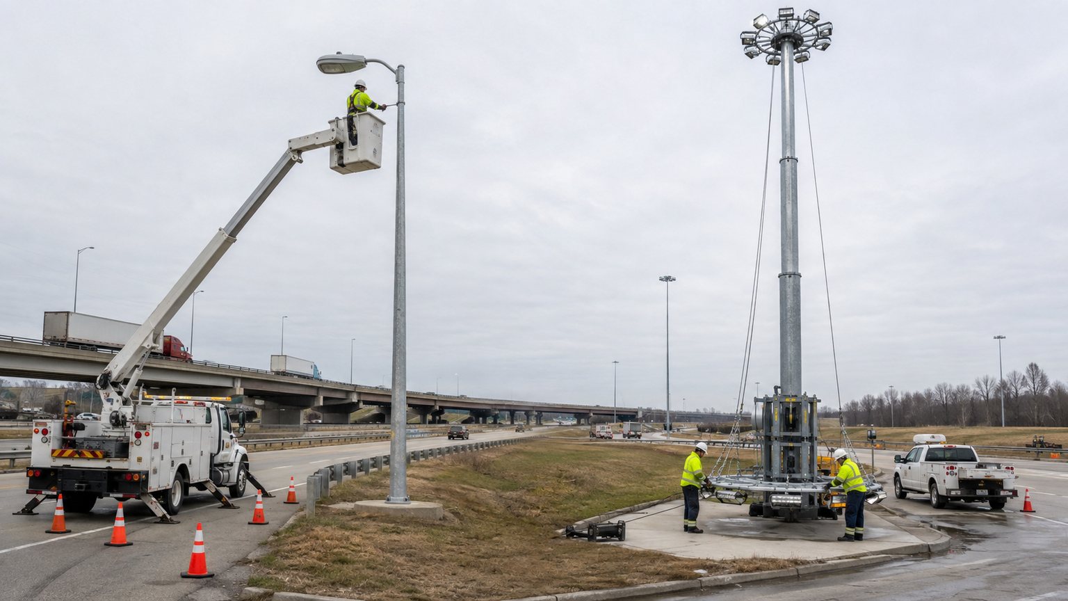
Street-light luminaires are commonly serviced from a bucket truck or elevated work platform. That method is familiar, but each pole requires safe vehicle positioning, stabilization and traffic control. On a narrow ramp shoulder, the work zone may close a lane or need night-time protection. More pole locations also mean more travel and setup operations over the life of the installation.
A raising-and-lowering high mast can bring the luminaire carriage to ground level for inspection and replacement. This can reduce work at height, but it does not eliminate maintenance planning. The lowering area must remain clear, the winch and cables need scheduled inspection, and technicians need training and controlled access. Buyers should compare complete maintenance procedures and spare-parts strategy rather than assuming either method is automatically cheaper.
A lowering system normally includes a head frame, moving carriage, suspension or hoisting ropes, power cable arrangement, latching mechanism where specified, winch and operating interface. The design should state how the carriage is guided, how the operating load is controlled, how accidental movement is prevented and what inspections are required. Compatibility among these components is more important than purchasing each item from an isolated schedule.
The tender should identify the preferred operating method, power source, access-control arrangement, required test and inspection records, spare ropes or components, and manuals. It should also define the lowered maintenance position and the clear ground area. The final equipment must follow the approved supplier design and local safety requirements; maintenance staff should not improvise a lowering procedure from a generic description.
Installation involves excavation, concrete work, delivery, lifting, wiring and commissioning. Roadway poles may be erected with smaller lifting equipment but at many locations. High-mast sections and head assemblies require larger cranes, controlled assembly space and a lift plan matched to tower height and weight. Access routes, overhead lines, bridge clearances and traffic staging should be checked before equipment reaches the site.
Maintenance planning should document which lanes or shoulders are occupied, the protection arrangement, permitted work periods and emergency procedures. A solution that performs well photometrically but requires frequent closure of a critical ramp may be undesirable. The owner should evaluate access throughout the asset life, including vegetation growth, new barriers and future road widening that could block the original service position.
A meaningful lifecycle comparison includes more than the pole or tower purchase price. Initial cost can include luminaires, structures, arms or carriages, foundations, anchors, cabling, cabinets, controls, delivery, cranes, traffic management and commissioning. Operating cost includes energy under the agreed control schedule. Maintenance cost includes inspection, cleaning, access equipment, lane management, replacement parts and staff time.
The analysis period, discount method, energy rate, maintenance intervals and replacement assumptions should be stated. A high mast may reduce the number of service points but use specialized lowering components. Roadway poles may use familiar equipment but require more roadside visits. Site-specific civil work can outweigh equipment differences. Transparent assumptions allow the owner to revise the comparison when traffic or commercial inputs change.
If some inputs are unavailable during budgeting, the proposal should list its assumptions clearly and identify items requiring confirmation. That approach is safer than presenting an apparently exact schedule built on hidden defaults.
A coordinated submittal normally includes a general arrangement, shaft sections, steel grades, wall schedule, joint details, base plate, anchors, access opening, bracket or carriage, luminaire interfaces, cable route and surface treatment. Structural design criteria and base reactions should match the approved accessory loads. High-mast documentation should additionally identify the raising-and-lowering arrangement and its inspection or operating requirements.
Quality documentation may include material records, dimensional checks, weld inspection scope, galvanizing or coating records, assembly checks and packing lists as agreed in the contract. Submittals should distinguish standard production controls from project-specific third-party inspection or certification. Jieyao can configure a combined roadway-pole and high-mast package after receiving the project criteria; production details are finalized through approved drawings.
Height does not define optical performance or structural capacity. Provide luminaire data, wind basis, bracket geometry and site conditions.
Equal wattage can produce different distributions and glare. Base decisions on verified photometric files and maintained calculations.
Soil, reactions, groundwater and geometry change by location. Coordinate the approved anchor plan with local civil design.
A lowering carriage or bucket truck needs a defined safe work zone that remains available after the road opens.
Cameras, signs and antennas add wind area and torsion. Include them in the approved structural load case.
State who supplies luminaires, controls, internal wiring, anchors, foundations, erection, testing and commissioning.
Separate ramps, approaches, bridge sections, central fields, boundaries and maintenance access areas.
Test roadway-pole, high-mast and hybrid layouts with verified luminaire photometric files.
Overlay utilities, drainage, structures, clear zones, soil conditions, wind exposure and delivery access.
Assess energy scenes, traffic management, access equipment, lowering systems and spare-parts needs.
Approve mounting, loads, bases, anchors, conduits, controls and responsibility boundaries.
Issue coordinated drawings, schedules, inspection requirements, packing plan and installation information.
No. Compare the complete lighting, foundation, electrical and maintenance costs.
Many projects evaluate 10–12m poles, but photometric design sets the final height.
Consider it for broad, open zones where several lower poles would be difficult to place.
Yes. High masts can cover central zones while roadway poles follow ramps and approaches.
No. Compare the total luminaire load and operating schedule.
The supplier provides reactions; a local civil engineer verifies the final foundation.
Provide the code, wind speed, exposure, topography and luminaire EPA.
No. The winch, ropes, carriage and electrical parts still need inspection.
Only after their loads and positions are structurally reviewed.
Send the site plan, lighting criteria, wind basis, luminaire data, quantity and destination.
No. Final quantities should follow an approved photometric layout.
State the galvanizing or coating standard, environment, color and inspection requirements.
Send Jieyao the road plan, required lighting criteria, candidate luminaire data, wind basis, site constraints, maintenance preference and commercial scope. We can help organize a project-specific package of roadway poles, high-mast towers, brackets, anchors and technical submittals for review. Final performance and structural details follow approved project inputs and drawings.
Send Project Drawings and RequirementsContact Us
Get a custom lighting solution and quotation for your project. Outdoor lighting manufacturer in Yangzhou, ChinaAbout Jieyao LightingYangzhou Jieyao Lighting Equipment Co., Ltd. is an outdoor lighting manufacturer focused on solar street light systems and high mas... Do you have any questions or requests?
Email: jay@jieyaolighting.com

Click to Chat.
Im online now.