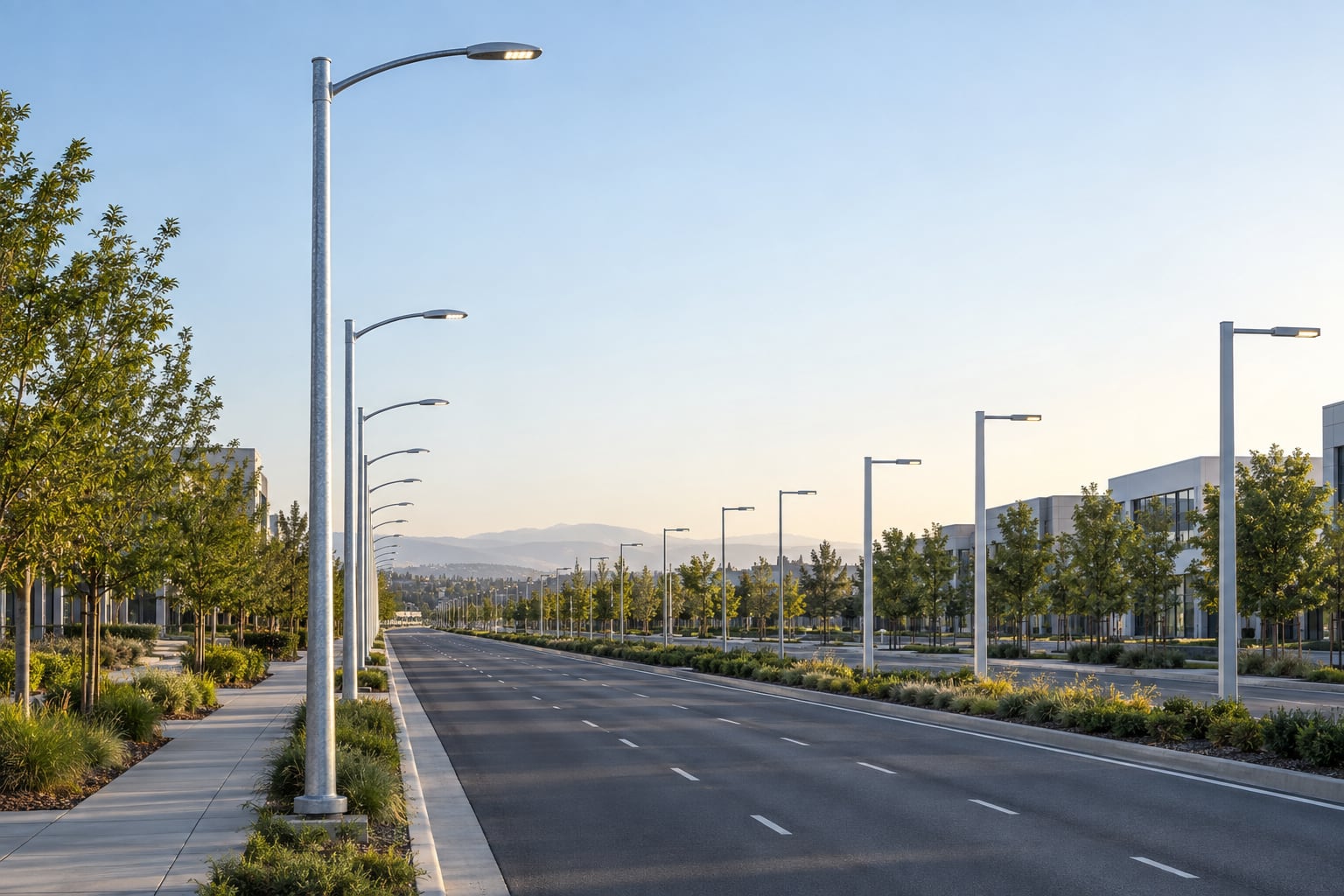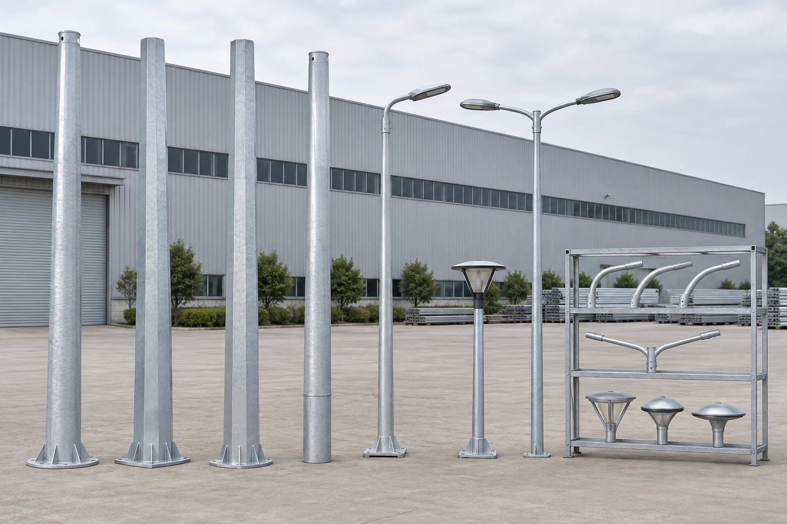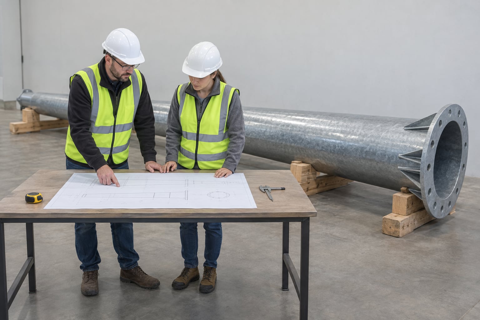


Configure galvanized steel lighting poles around the actual road layout, mounting height, shaft shape, arm, luminaire load, wind basis, base type, coating, drawings, inspection and delivery plan.
A street light pole is a structural support that places one or more luminaires at the coordinates required by a road or area lighting design. The complete assembly can include a tapered or straight steel shaft, arm or top adaptor, luminaire interface, service opening, base connection, internal cable route, earthing provision, corrosion protection and project identification.
The phrase describes a product family, not one universal model. Height, shaft geometry, wall schedule, steel grade, arm outreach, fixture mass and effective projected area, wind basis, base plate or embedment detail, coating and documentation change from project to project. A useful quotation therefore begins with a pole schedule and stated design inputs rather than one isolated dimension or an incomplete commercial figure.
A street light pole manufacturer translates lighting, structural, civil, electrical, architectural and logistics requirements into one controlled supply package. The work is not limited to forming a steel tube. Arm position, luminaire fit, wind loads, access-door reinforcement, cable routing, plate and anchors, galvanizing, marking, packing and site assembly must refer to the same approved configuration.
Jieyao organizes these decisions by pole mark. Each mark links the road location, mounting height, shaft, arm, fixture, base and finish to the applicable drawing and inspection record. This approach helps contractors, distributors and consultants compare like-for-like offers and identify information that remains open before production release.
Galvanized steel street light poles can be configured for municipal streets, urban arterials, industrial roads, warehouse yards, parking areas, campuses, residential access routes, port approaches and selected highway locations. Each environment creates different visual, clearance, maintenance, exposure and collision considerations even when the nominal height is similar.
Start from the lighting zone rather than assigning one pole across an entire development. A median, verge, pedestrian route and loading yard may need different arms, door orientations, fixtures or bases. Divide mixed sites into controlled marks and retain those marks through drawings, foundation coordination, manufacturing, packing, erection and handover.
A pole schedule should list application, quantity, height reference, shaft shape, arm geometry, luminaire model, mass, EPA, center of gravity, wind basis, base type, access orientation, finish and documentation. If a value is not final, identify the responsible party and approval hold point instead of filling the gap with an assumed standard.
Use a unique mark for every configuration. Two poles described as 10 m may differ in arm outreach, fixture load, door direction, anchor pattern and reaction schedule. Stable marks prevent the optical design from changing while the structural or civil package remains based on an earlier fixture.
A round tapered shaft presents a continuous circular profile and non-directional appearance. It can suit roadway, commercial and campus projects where a clean visual line is preferred. Round geometry influences clamps, base covers, door frames and arm transitions, and the lower and upper diameters must be defined at agreed measurement points.
Round does not mean one standard wall thickness or wind capacity. Height, taper, steel, seam, opening, top load and base connection remain design inputs. Review the round tapered galvanized steel light pole page for shape-specific procurement and inspection questions.
A square tapered shaft has four flat faces and defined corners. It can align visually with rectilinear buildings, curbs and contemporary area-lighting layouts. Face orientation affects appearance and can also determine the relationship among the arm, access door, base plate and directional loading review.
Specify face-to-face dimensions and distinguish them from measurements across corners. Accessories made for round or octagonal sections should not be assumed to fit. The square tapered galvanized steel light pole page covers four-sided geometry, orientation, interfaces and packing in more detail.
An octagonal shaft is formed with eight faces and approaches a circular outline while retaining defined bends. Polygonal geometry is widely considered for conventional road lighting because it can be tapered, nested for transport in selected designs and inspected by controlled across-flats dimensions. The actual benefits depend on the complete configuration.
Across-flats size, taper, wall schedule, seam location, opening and base must be coordinated. More faces are not automatic proof of greater strength. Use the dedicated octagonal galvanized steel street light pole page when the tender or visual concept calls for an eight-sided shaft.
Use this shape table to compare the drawing questions, not to rank one profile as universally stronger or cheaper. Each option still needs the same project-specific luminaire, wind, opening and base review.
| Shaft profile | Geometry to define | Accessory check |
|---|---|---|
| Round tapered | Lower/upper diameter and taper reference | Clamp, door frame, arm transition and base cover |
| Square tapered | Across-faces dimension and face orientation | Arm/door alignment, corners and directional base detail |
| Octagonal tapered | Across-flats dimension, bends and seam location | Bracket face, opening and fit-up pattern |
| Straight section | Constant outside dimension and full shaft length | Top and base transitions under the checked actions |
A tapered shaft places a larger section near the base and reduces toward the top. A straight shaft keeps a constant outside dimension where the structural and architectural design supports that form. Longer poles may use approved segments when manufacturing, galvanizing, container loading or site access makes a one-piece shaft impractical.
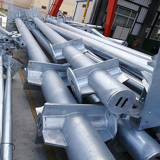
A sectional joint is part of the structure and must be designed, drawn, trial-checked where required, protected during shipping and assembled by a controlled site method. Define engagement, alignment, match marks, fasteners or slip-joint requirements and cable passage. Do not cut a finished one-piece pole into transport lengths without engineering review.
Mounting height affects pole spacing, illuminance, uniformity, glare, fixture output, structural demand, foundation reactions and maintenance access. It should follow a photometric model using the proposed luminaire, optic, road geometry, surface data, tilt and maintenance assumptions. Road width alone is not enough to fix a safe or efficient height.
State whether a height means shaft length above the base, luminaire mounting height or overall height including arm rise. For controlled height-specific intent, review the 8m galvanized pole, 10m single-arm pole, 10m double-arm pole, 12m highway pole and 15m highway pole.
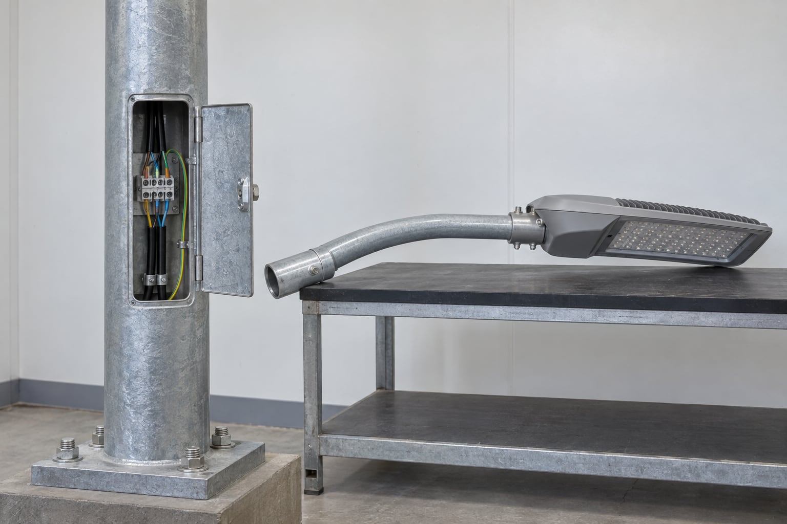
A single arm places one roadway luminaire at a defined horizontal and vertical coordinate from a verge, shoulder or one-sided mounting position. Straight, curved and upswept arms create different outreach, rise, inclination and architectural results. The arm must be treated as part of the structural load and internal conductor path.
Provide arm geometry, tube size, connection, mass, orientation and luminaire interface. If arms ship separately, show engagement, fasteners, anti-rotation, match marks and cable-edge protection. A field-drilled or improvised adaptor can compromise alignment, galvanizing and structural assumptions.
Twin arms can serve a central median or two-sided lighting zone when the photometric layout and structural design support the arrangement. Symmetry in appearance does not remove torsion, unequal fixture conditions or directional wind. Each luminaire and arm must be included in the load schedule.
Show arm orientation relative to the road centerline, shaft seam, door and base. Confirm whether the two fixtures are identical and whether future maintenance can reach both sides safely. Separate left- and right-hand marks may be required when road geometry, tilt or clearance differs.
A post-top adaptor can place a suitable luminaire directly above the shaft, while custom arms can achieve project-specific mounting coordinates or appearance. The interface should define spigot diameter, insertion length, fasteners, anti-rotation, allowable tilt, cable entry and access after installation.
Do not select an adaptor from a fixture photograph. Use the current dimensional drawing and confirm housing mass, EPA and center of gravity. If the luminaire model changes, repeat fit and load checks before production. A compatible mechanical connection does not automatically confirm optical or structural suitability.
Structural selection needs the governing standard, basic wind parameter, exposure or terrain category, topographic condition, height reference, project risk provisions and applicable load combinations. A wind speed without its basis cannot establish capacity because standards use different averaging periods, factors and calculation methods.
Record the site coordinates and special conditions such as open coast, escarpment, bridge approach or elevated foundation. The supplier can then state the assumptions used for the shaft and connection. Where local law or the contract requires review by a licensed engineer, agree the responsible jurisdiction and submission scope before the order.
Effective projected area is not necessarily the simple front-face area measured from a photograph. Provide the fixture manufacturer's declared data for the relevant orientation, together with mass, center of gravity and mounting position. Include arms, signs, cameras, control boxes, banners and future equipment that belongs in the design.
Wattage is electrical information, not a structural load. Two luminaires with similar output can have different housings, projected areas and centers of gravity. When equipment changes after approval, revise the affected pole mark and repeat structural and photometric review instead of assuming the original pole remains suitable.
Steel grade is one element of the design. Yield properties, available plate, forming behavior, wall thickness, taper, longitudinal seam, openings and base connection work together. A named material does not justify one wall thickness for every height, wind condition or fixture arrangement.
The shop drawing should identify the applicable material and section schedule for every pole mark. If the shaft uses multiple segments or thicknesses, show transitions clearly. Avoid vague descriptions such as heavy duty unless the proposal also states the geometry, load basis and interfaces that create the offered configuration.
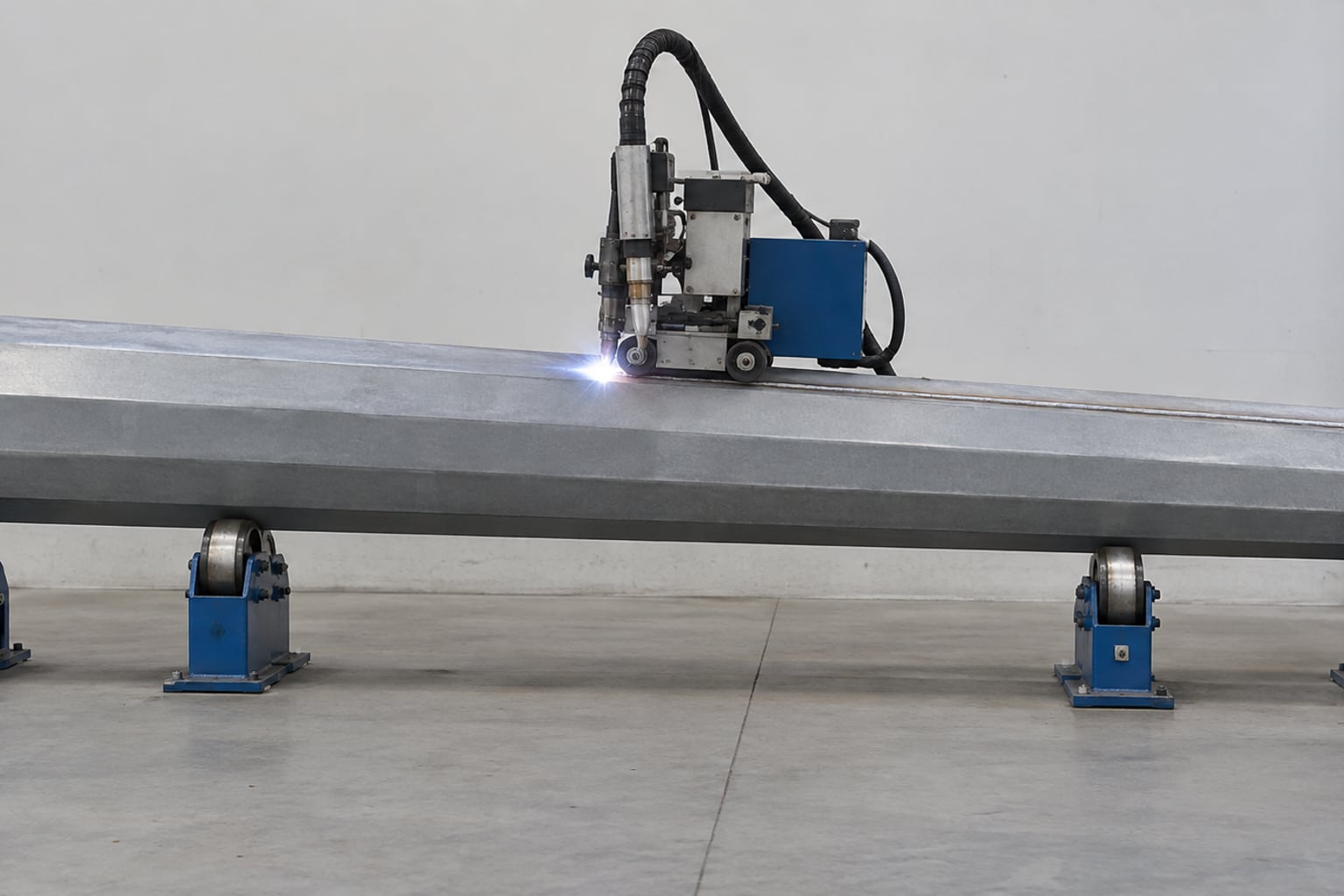
A tapered steel shaft begins with a developed plate blank that is cut and formed along controlled lines. Forming sequence, tooling, material behavior and fit-up influence taper, straightness, face dimensions and twist. The longitudinal seam closes the shell and participates in the structural load path.
Welding follows the approved procedure and inspection plan. Heat input can affect straightness, while excessive grinding can reduce local thickness. Cosmetic smoothing is not a substitute for weld quality. Openings, reinforcements, base details and arm interfaces should remain connected to the correct drawing revision throughout fabrication.
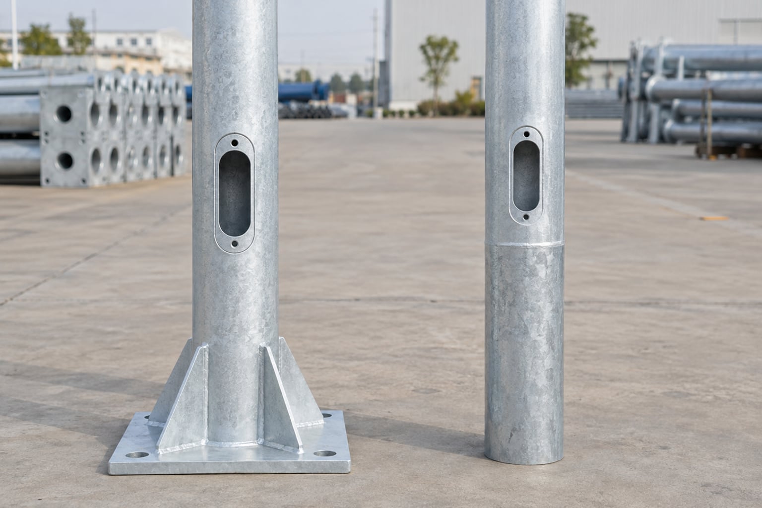
The lower access opening must provide workable entry to terminals, protective devices or cable joints while preserving the shaft load path. Define its elevation, orientation, dimensions, frame, reinforcement, cover, gasket, fasteners and earthing provision. Door position should avoid traffic impact and remain accessible after paving, barriers and landscaping are complete.
Opening size is not a convenience decision. It changes local section behavior and can interact with the shaft seam, base weld and internal cable route. Keep conductors supported and protected from sharp edges, standing water and anchor hardware. Replacement covers should match the opening rather than relying on improvised field drilling.
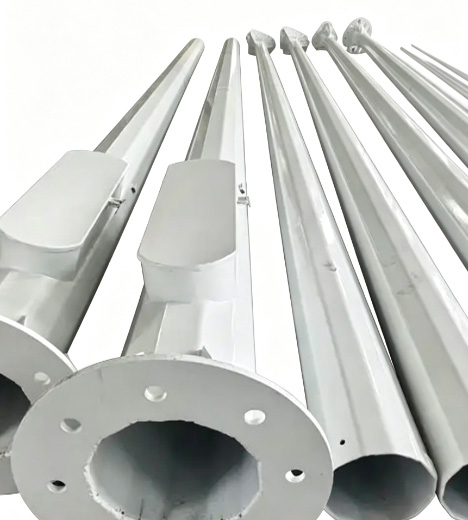
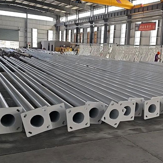
A flanged-base pole uses a welded plate secured to a concrete foundation by an engineered anchor assembly. Shaft, weld, plate, holes, anchors, nuts, washers, support condition, grout where required and concrete design form one load path. Plate width or anchor diameter alone does not define the capacity.
The final plate and anchor interface should be approved before foundation work is released. The flanged base galvanized steel light pole page covers plate geometry, anchor templates, conduit coordination, foundation reactions and erection checks for buyers using this mounting concept.
A direct-burial pole extends below finished grade and transfers actions through an embedded shaft zone and surrounding foundation material. Embedment length, lower-shaft protection, cable entry, drainage, backfill or concrete interface and erection method must be designed for the project. A flanged pole should not be converted by simply extending its tube.
The direct burial galvanized street light pole page owns embedded-shaft procurement intent and explains the civil information required. Neither direct burial nor flange mounting is universally better; selection depends on soil, specification, exposure, maintenance and project responsibility.
The two lower ends need different civil and service information. Use this table as a quotation-scope check; the responsible project designer still approves the installed foundation.
| Lower-end option | Civil interface to release | Service/finish coordination |
|---|---|---|
| Flanged plate and anchors | Base reactions, plate/bolt pattern, template and concrete design | Conduit opening, grout or support detail, anchor access and repair |
| Direct-burial embedded shaft | Embedment, soil/backfill or concrete interface and installation method | Below-grade protection, cable entry, drainage and replacement approach |
The pole supplier can provide approved base reactions and the steel interface within the agreed scope. The responsible foundation designer evaluates soil, concrete, reinforcement, embedment, drainage, utilities and governing civil requirements. Clearly assigning these roles prevents a copied footing sketch from being treated as a complete site design.
Anchor templates, conduit position and reinforcement must match the released pole base. Check them before concrete and before lifting. The street light pole foundation and anchor bolt guide provides a structured information exchange without presenting one foundation size as suitable for every site.
Hot-dip galvanizing applies a zinc coating to prepared steel after principal fabrication is complete. Hollow shafts require suitable venting and drainage for processing, and geometry around seams, plates, stiffeners, openings and arms influences zinc flow and inspection access. The applicable coating standard and acceptance method should be stated in the purchase specification.
Galvanizing is not a universal service-life guarantee. Exposure, design details, coating condition, installation damage and maintenance affect performance. Define any permitted repair method before shipment and avoid unapproved field grinding or drilling. Records should identify the pole marks and components covered when the contract requires coating documentation.
A compatible organic coating over galvanizing can add a selected color and another barrier layer. Specify surface preparation, pretreatment, primer or intermediate layer where applicable, topcoat, color, gloss, texture, masking, repair and inspection. The coating-system supplier's compatibility instructions should govern the sequence.
Approve a representative color sample when visual matching matters. Threads, earthing points, mating surfaces, identification and assembly zones may require controlled masking. Pack finished parts with padded separators so shafts, doors, arms and base covers do not rub during container loading and inland transport.
Marine aerosol, persistent humidity, industrial contaminants, standing water and coating damage can change the corrosion-control strategy. Document the exposure rather than relying only on the word coastal. Review drainage, crevices, fasteners, base-zone details, door seals, material compatibility, maintenance access and any duplex system as one package.
The coastal road duplex-coated lighting pole page covers exposure-led procurement in more detail. Final coating thickness, preparation, inspection and maintenance requirements follow the selected standard and project environment; they should not be replaced by an unsupported online lifespan claim.
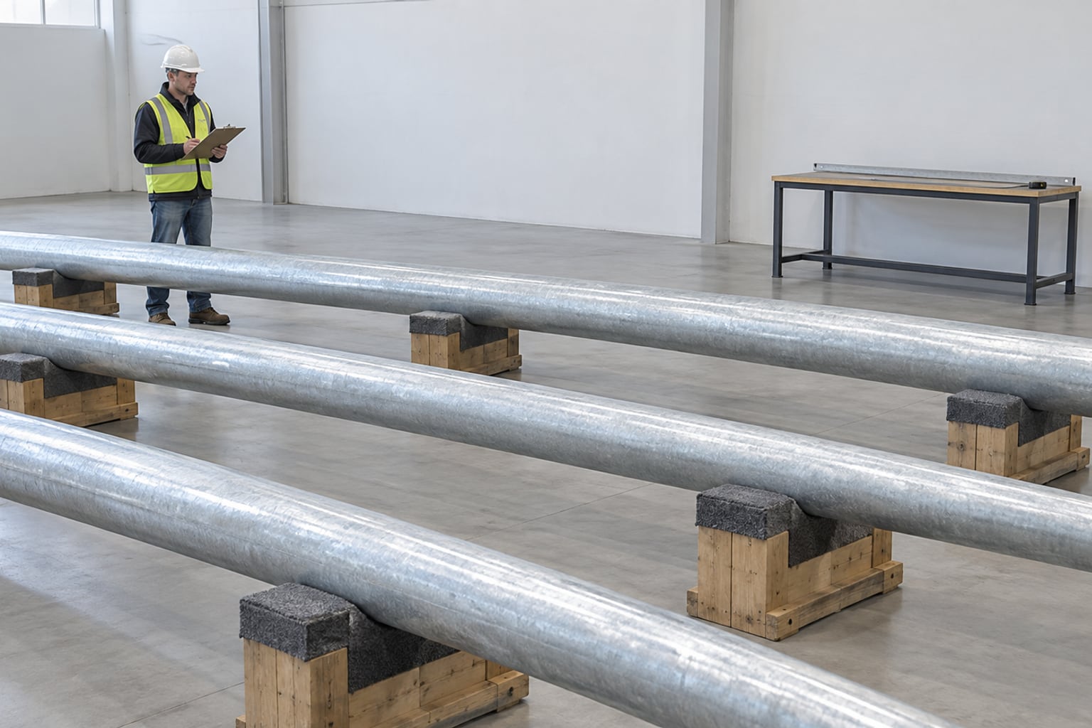
Inspection can cover material identity, blank dimensions, formed geometry, taper, straightness, seam, openings, base, arm interface, galvanizing, accessories, marking and packing. The scope and acceptance criteria should follow project risk and specification. Not every pole needs the same examination, but required hold points should be known before production begins.
Support long shafts correctly during measurement so deflection or handling damage does not create a misleading result. Link records to pole marks and drawing revisions. Where trial assembly or additional examination is required, define the method and responsible reviewer rather than making a broad claim that every product receives every possible test.
A useful general arrangement states the height reference, shaft dimensions, taper, wall schedule, arm geometry, luminaire interface, access opening, base, cable route, finish, orientation and mark. Detail sheets clarify welds, reinforcements, doors, templates, covers and joints. Reaction schedules must match the shown configuration.
Review lighting, structural, civil and electrical information together. The street light pole shop drawing checklist provides a controlled approval sequence. Close comments and update affected sheets before releasing materials; an approved elevation does not automatically approve the anchors or foundation.
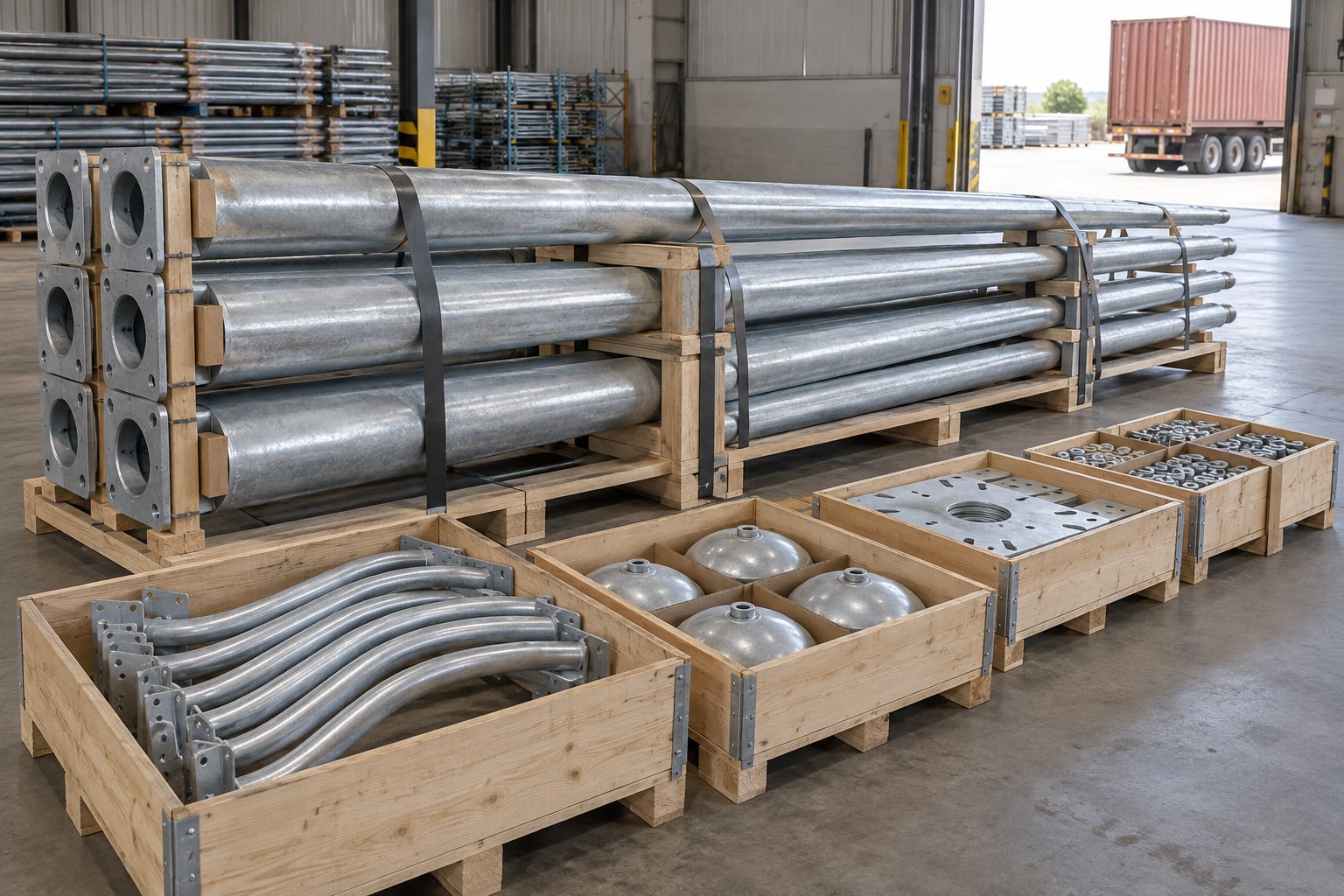
Use stable timber supports, padded separators and restraints suited to the container and handling route. Protect shaft surfaces, plate corners, doors and top interfaces from point loads and rubbing. Arms, covers, anchor templates, nuts, washers, adaptors and fasteners should be grouped in protected crates linked to their pole marks.
A packing list should identify every bundle and accessory group without relying on appearance. At receiving, count and inspect materials before they are distributed around the site. Store shafts on level supports away from standing water, contamination and vehicle movement, and keep identification visible until erection.
Before lifting, confirm pole mark, foundation or embedment readiness, anchor pattern where used, conduit access, surrounding clearances, lifting points, equipment capacity, exclusion zone, weather limit and current drawing. Do not use a crane to force a mismatched plate, shaft or arm into position.
After erection, check orientation, plumbness, approved fastener condition, cable protection, earthing, arm engagement, luminaire tilt and service-door closure. The project erection method statement should organize receiving, civil release, lifting, wiring, commissioning and handover without treating one installation method as universal.
Parking areas need pole locations that support the photometric layout while avoiding vehicle paths, accessible routes, drainage, landscaping and maintenance conflicts. Single or multi-fixture heads, mounting height, shielding and base protection depend on the site. Structural inputs must include every luminaire and bracket orientation.
The galvanized steel parking lot light pole page addresses area-lighting procurement intent. It should be used with a project-specific lighting model rather than a universal spacing ratio or fixed pole-height rule.
Decorative poles coordinate structural demand with proportions, arm form, base cover, color, door integration and the surrounding streetscape. Ornamental elements do not replace the structural shaft and may add projected area, mass, crevices and coating interfaces that need review.
Use the decorative galvanized street light pole page for appearance-led procurement. Approve the complete shaft, luminaire and ornament assembly, and keep removable covers accessible for inspection rather than using them to conceal unresolved base or drainage conditions.
A pole carrying traffic signals, mast arms, signs, cameras or multiple service systems has different load, access, electrical and approval requirements from a conventional roadway lighting pole. Similar appearance does not make the products interchangeable. Use separate marks and calculations for mixed infrastructure rather than adding attachments after the lighting pole has been approved.
For combined roadside equipment, review the multi-function traffic signal pole and the applicable traffic-pole scope. The smart-pole-versus-light-pole selection guide helps compare a shared support with a lighting-only arrangement when optional services are actually defined. Identify every arm, signal head, sign, controller and future device instead of claiming that one shaft can accept every module.
Maintenance access should be considered when pole locations and mounting heights are selected. Confirm that safe equipment can reach the luminaire and that the service door remains accessible after curbs, barriers, planting and paving are complete. Record the approved arm, spigot, door and terminal arrangement for future parts review.
A replacement luminaire that physically fits can still have different mass, EPA, center of gravity, electrical demand or optical performance. Review changes before installation. Unauthorized holes, clamps, banners and cameras can affect stress, water paths and coating condition, so future attachments should be checked against the recorded load basis.
Do not order a replacement from height and appearance alone. Verify shaft shape, lower and upper dimensions, taper, wall schedule, plate and hole pattern or embedment detail, arm, luminaire loads, door orientation, finish and foundation condition. Existing anchors and concrete need assessment by the responsible project team.
Where original records are incomplete, obtain controlled measurements and identify uncertainty in the enquiry. Do not treat slotted holes, enlarged openings or bent anchors as routine fit-up solutions. A replacement proposal should state which interfaces are retained, which were verified and which require civil or engineering modification.
Frequent omissions include an undefined height reference, fixture wattage without mass or EPA, arm outreach without rise, wind speed without governing basis, a base plate without anchor data, a door without orientation and color without a coating system. Another error is copying wall thickness or foundation dimensions from a different site.
Use hold points: confirm the lighting layout and equipment loads, establish the structural basis, approve pole and base drawings, release foundations, verify site interfaces and then erect. Ask each bidder to list assumptions and exclusions. A clearly open item is safer than a precise-looking dimension supported by incomplete inputs.
Align pole marks, steel, shaft geometry, arms, adaptors, luminaires, plates, anchors, doors, terminals, galvanizing, duplex coating, calculations, drawings, inspection, packing and delivery before comparing offers. A lower commercial offer can reflect a missing component or different load assumption rather than better value.
Require the proposed standard, wind inputs, top loads, material, section schedule and interfaces to be stated. Confirm document and inspection scope without assuming that every supplier includes the same items. Commercial comparison becomes more useful after open technical differences have been identified and normalized.
The handover package can connect as-built pole marks with approved drawings, reaction or calculation schedules, material and coating records where specified, dimensional inspections, packing information and site checks. The exact scope follows the contract. Clear indexing matters more than collecting unrelated documents.
Remove superseded drawings from the installation set and identify which records cover each batch. Preserve luminaire loads, arm geometry and foundation interfaces because they support future maintenance and replacement. A service team should be able to trace the installed pole to the correct approved information.
Send the project location, application, quantity by pole mark, mounting-height definition, lighting layout, arm geometry, luminaire model and interface, mass, EPA, center of gravity, wind basis, preferred shaft shape, base concept, door orientation, electrical needs, finish, inspection, documents, packing and delivery constraints.
If some inputs are preliminary, label them openly and identify the decision date. Available civil, architectural and luminaire drawings can reveal clearances or interfaces that a text schedule misses. A manufacturer can organize options and questions without presenting provisional dimensions as approved values.
Jieyao starts with the pole schedule, lighting coordinates, equipment loads, wind basis, shaft and mounting preference, finish and logistics route. The review separates fixed requirements from options and missing information. A project-specific proposal then connects supplied components, interfaces, drawings, inspection and packing to the same pole marks.
The objective is a buildable supply package, not a universal online specification. Final height, section, wall schedule, arm, plate, anchors, embedment and coating follow the approved project basis. Send the available documents through the contact page; clearly recorded questions can be closed before material and civil release.
Height, shaft, arm, fixture loads, wind basis, base, access, finish and documents define it together.
Use the photometric design, road geometry, fixture and maintenance plan to select mounting height.
No shape is universally best. Compare appearance, interfaces, section and project loads.
Yes, when the lighting layout, arm geometry, fixture data and structural design support them.
Send model, interface, mass, EPA, center of gravity, insertion length and allowed tilt.
No. The standard, exposure, topography, height and complete attachments are also needed.
Choose through the project foundation, soil, exposure, specification and maintenance requirements.
Yes, with the applicable coating, inspection, venting, drainage and repair requirements.
Yes. Define a compatible duplex system, color, texture, masking and acceptance criteria.
The responsible foundation designer uses approved pole reactions and site-specific soil information.
Only after checking fit, mass, EPA, center of gravity, electrical data and the recorded design basis.
Send the pole schedule, lighting layout, loads, wind basis, base concept, finish and delivery scope.
Send your pole schedule, lighting layout, luminaire and arm data, wind basis, foundation concept and finish requirement. Jieyao will organize the open items and prepare a project-specific configuration for technical review.
Contact Jieyao
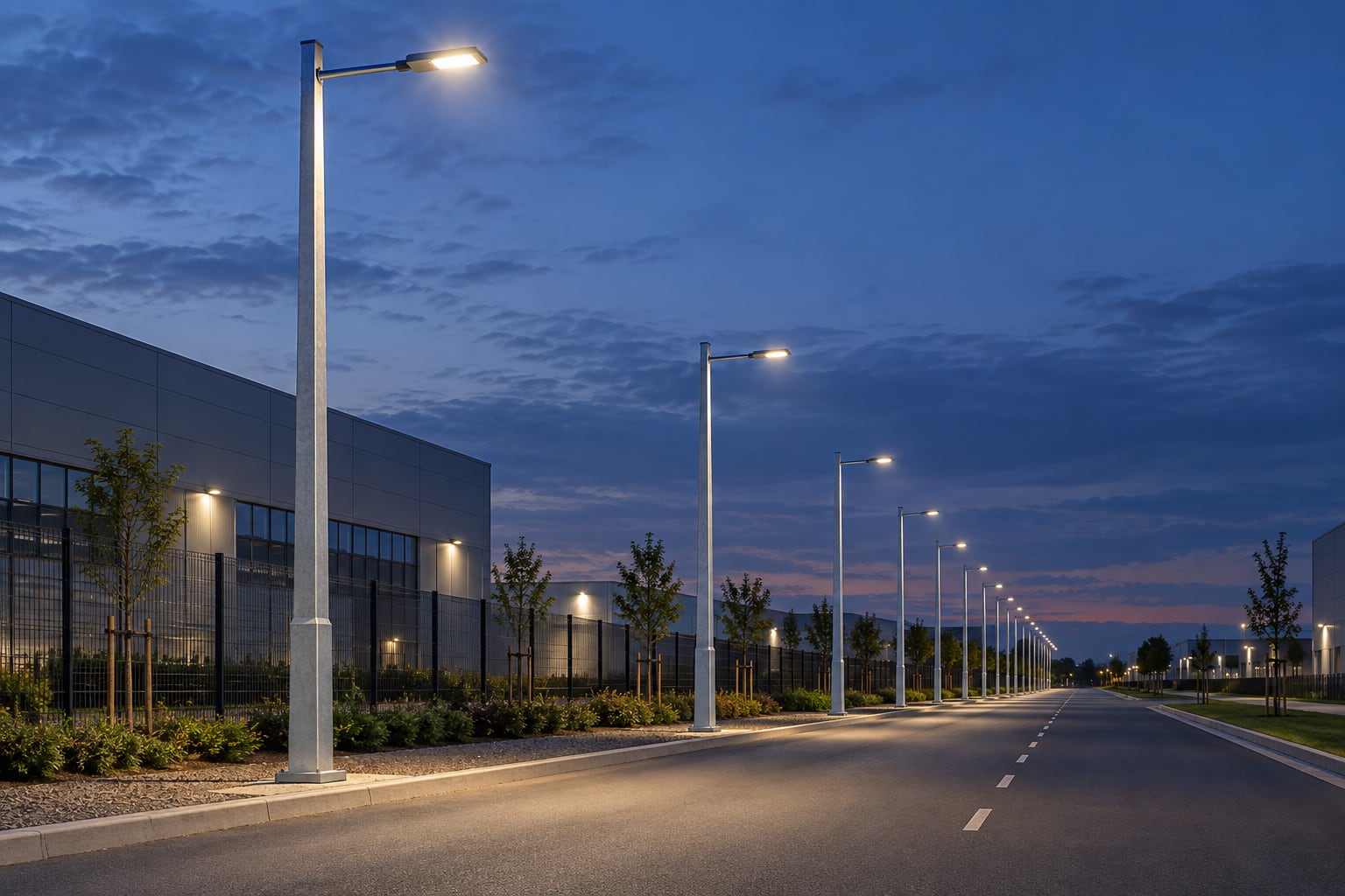
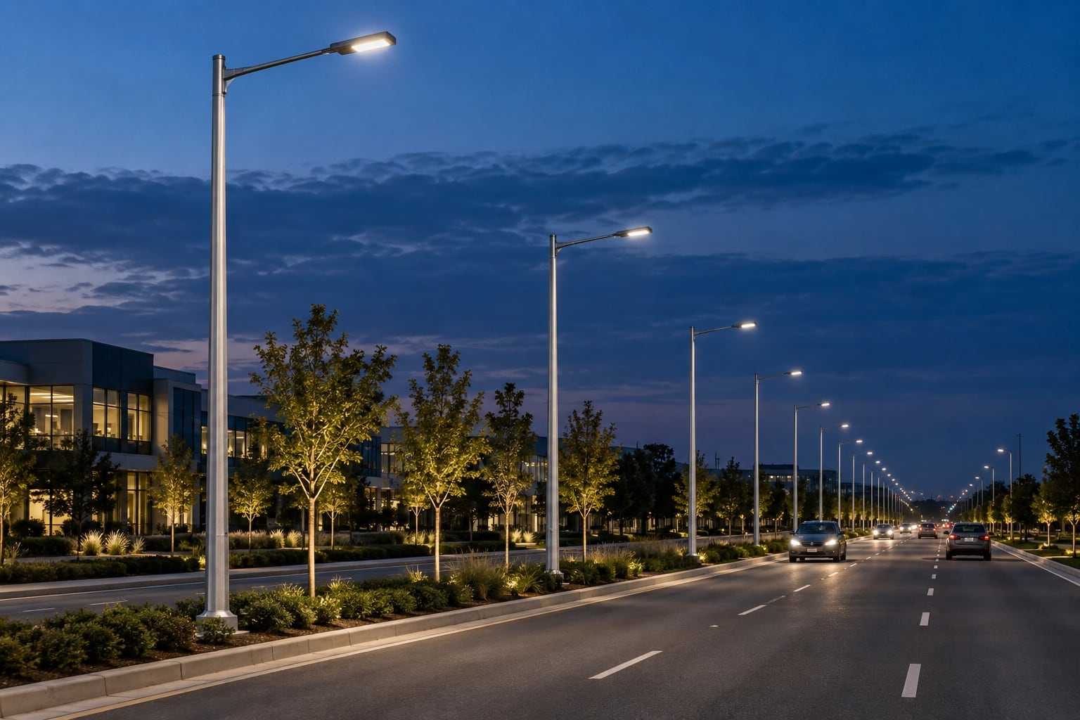
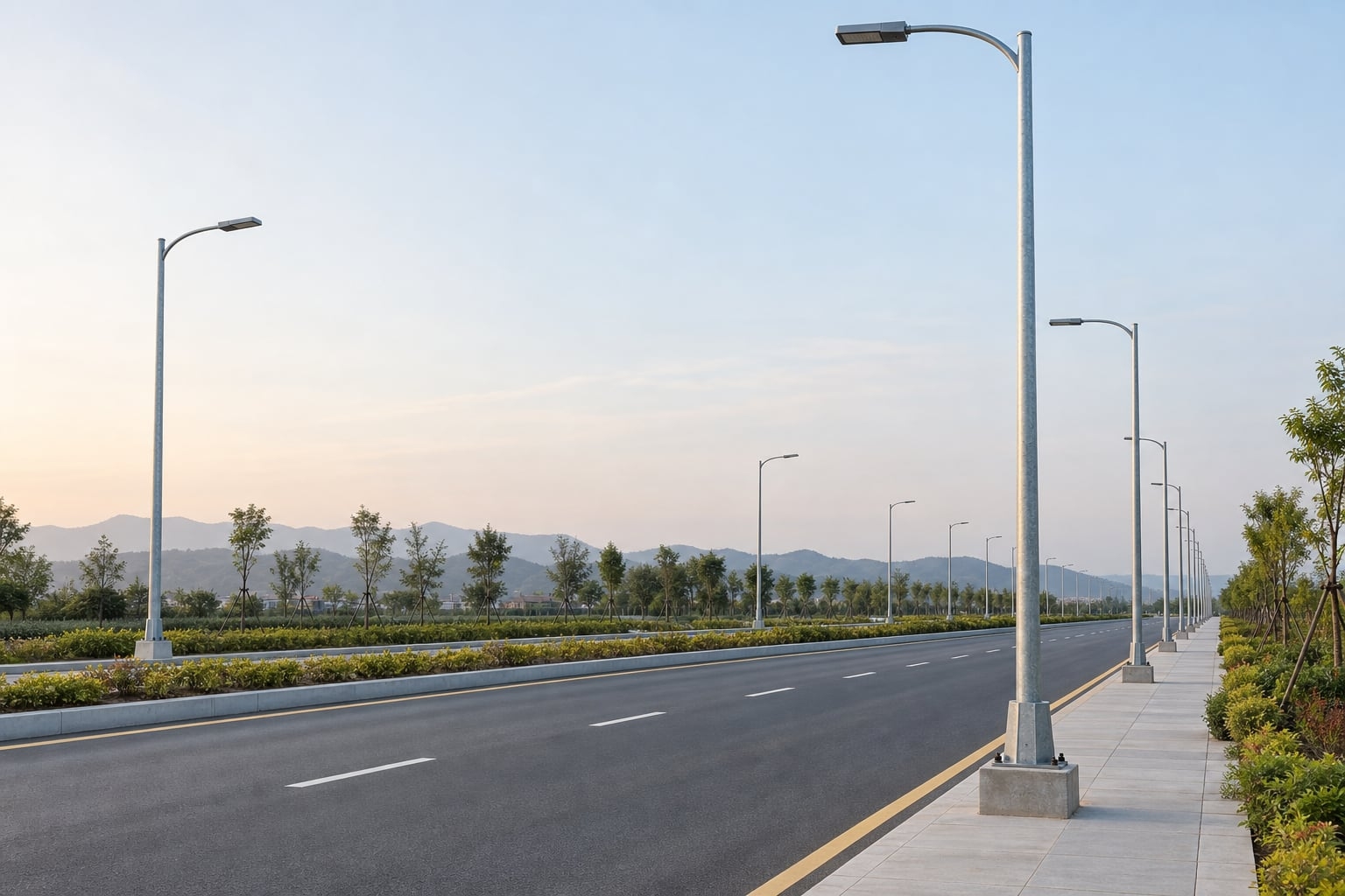
Plan a parking lot light pole layout with photometric files, protected pole locations, glare control, structural loads, foundations and maintenance access. Height and spacing are project-specific.
Learn how to choose lighting poles for airports and ports. Understand key selection standards including wind load resistance, corrosion protection, pole height, material choice, and safety requirements for aviation and marine environments.
Compare hot-dip galvanizing, direct-to-steel paint and compatible duplex coatings for street light poles by exposure, detailing, inspection and repair scope.
Compare galvanized steel, aluminum and stainless steel light pole assemblies by structural design, fabrication, corrosion control, finish, handling and inspection evidence. Select materials for the project exposure and approved supply scope.
Compare single arm and double arm street light poles for roads, highways, parking areas, and municipal projects. Learn the differences in lighting coverage, installation cost, application scenarios, and how to choose the right street light pole for long-term project performance.
The best pole for solar street lights depends on wind load, environment, and project scale. Learn when to choose steel, aluminum, or galvanized steel poles for different outdoor lighting applications.
Discover the life expectancy of street light poles based on materials like steel, aluminum, and concrete. Learn how climate, installation quality, and maintenance affect pole lifespan in real outdoor lighting projects.
Learn how to install a solar street light with pole step by step, including foundation construction, pole erection, wiring, and system testing. A practical guide for road lighting, parking lots, and outdoor solar lighting projects.
We primarily use high-strength carbon steel (Q235/Q345/ASTM A36). We also offer premium aluminum alloy and stainless steel poles specifically for coastal regions.
Tapered poles are aesthetic with low wind resistance; cylindrical poles are more cost-effective; polygonal poles (usually 8/12/16 sides) offer the highest structural strength, ideal for high mast lighting.
Our engineers perform mechanical calculations based on your local wind speed data, adjusting wall thickness and base design to ensure the poles can withstand winds up to 160km/h.
It typically ranges from 3mm to 12mm, depending on the pole height, weight of the fixtures, and local wind load requirements.
This is an anti-corrosion process of immersing steel in molten zinc. It provides over 25 years of maintenance-free rust protection in standard outdoor environments.
Yes. We provide complimentary foundation reference drawings, including concrete depth, rebar specs, and bolt positioning data.
We follow AWS welding standards and use Ultrasonic Testing (UT) or Magnetic Particle Testing (MT) to ensure welds are free of pores or cracks.
We hold ISO 9001 (Quality), ISO 14001 (Environmental), and CE certification (EN 40) specifically for the European market.
Yes. We can produce sample poles for craft and color confirmation, though sample shipping costs are typically covered by the client.
Steel poles are lighter, easier to transport and install, have a long lifespan after galvanization, and offer high scrap value, making them more eco-friendly.
Galvanized poles are virtually maintenance-free. We recommend checking anchor bolt tightness and the powder coating surface every 3-5 years.
We provide touch-up paint with each shipment. Simply clean the scratch and apply the paint to restore the appearance.
No. Base plate size and hole spacing are designed based on pole height and stress loads. We provide detailed dimensional drawings for each order.
These are accessories (like anti-climb spikes) installed on the lower section of the pole to prevent unauthorized climbing and enhance security.
Yes. We can flexibly adjust section lengths (e.g., 6m+6m or 5m+7m) based on logistics constraints and on-site installation conditions.
Contact Us
Get a custom lighting solution and quotation for your project. Outdoor lighting manufacturer in Yangzhou, ChinaAbout Jieyao LightingYangzhou Jieyao Lighting Equipment Co., Ltd. is an outdoor lighting manufacturer focused on solar street light systems and high mas... Do you have any questions or requests?
Email: jay@jieyaolighting.com

Click to Chat.
Im online now.