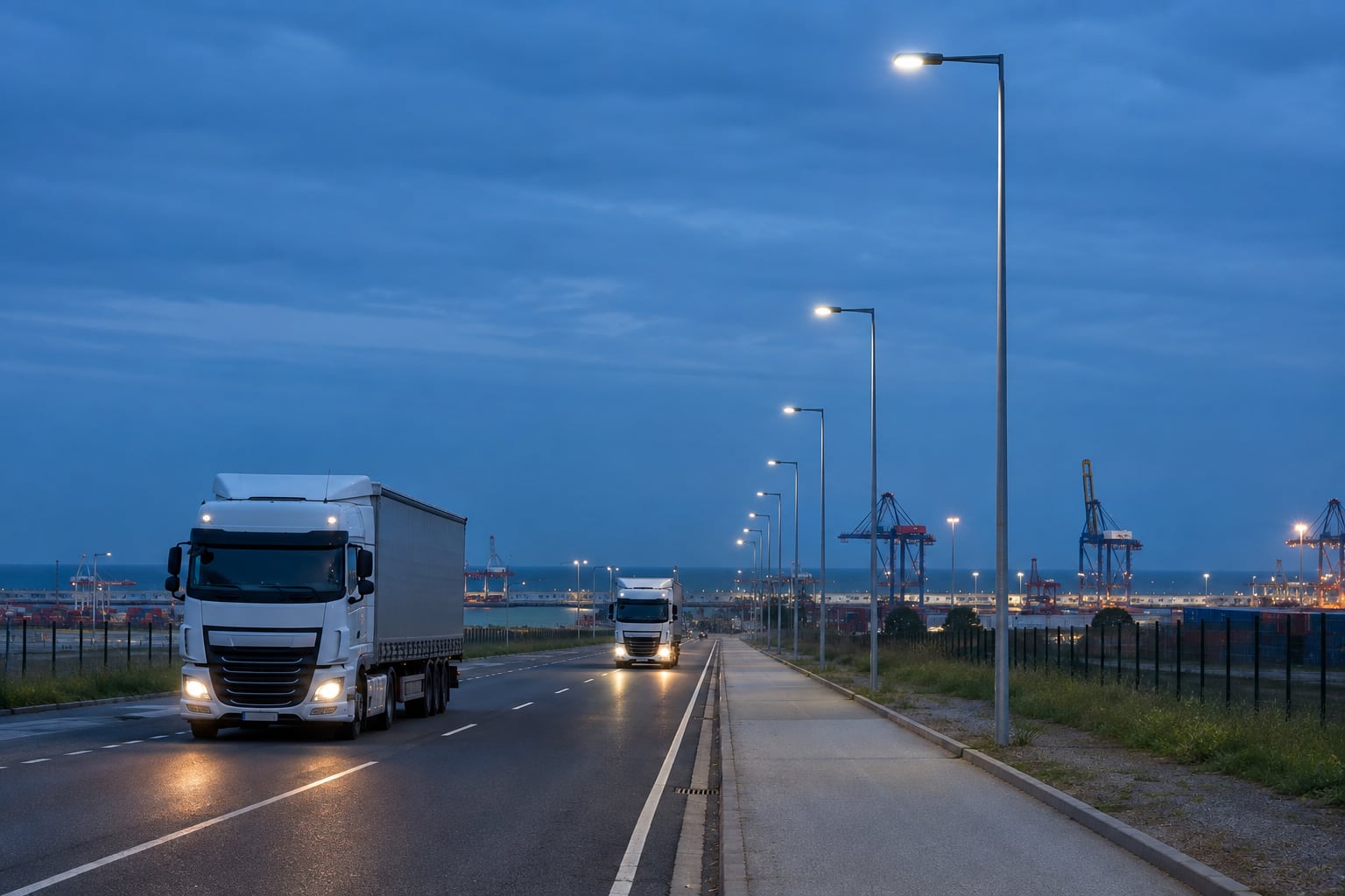
The road, gate and yard boundary need one coordinated lighting brief.
What should a port road lighting brief contain?
Start with a scaled route plan, design-vehicle swept paths, operating zones, conflict points, authority boundaries and the applicable lighting criteria. Add luminaire photometric files, preliminary pole positions, arm and attachment schedules, coastal exposure assumptions, underground services and maintenance routes. A pole height or wattage alone cannot define a compliant layout.
Separate the public-road approach, gate queue, internal truck route and road-to-yard transition. Each may have a different viewing task and operating state. The designer or authority sets the numerical criteria; the pole supplier needs those criteria and equipment loads to engineer the correct shaft, arm, base and finish.
Table 1. Route zones and the decisions to record
| Zone | Site evidence | Lighting and pole decision |
|---|
| Public approach | Road width, speed basis, existing lighting and authority limit | Criteria handoff, pole line and controls boundary |
| Gate and queue | Stop lines, booths, barriers, people and signs | Task visibility, glare, setback and impact protection |
| Internal truck road | Swept paths, turning areas, shoulders and services | Pole coordinates, outreach, access and foundation concept |
| Road/yard edge | Yard luminaires, obstructions and operating states | Photometric transition and separate control groups |
Coordinate trucks, pole positions and the road-to-yard transition
Overlay the design vehicle's swept path, mirrors, trailers and turning envelope on the pole plan. Check each proposed base against curbs, barriers, inspection bays, opening doors and the maintenance vehicle. At gates, confirm that pole and luminaire positions do not obstruct signs, cameras or driver sightlines.
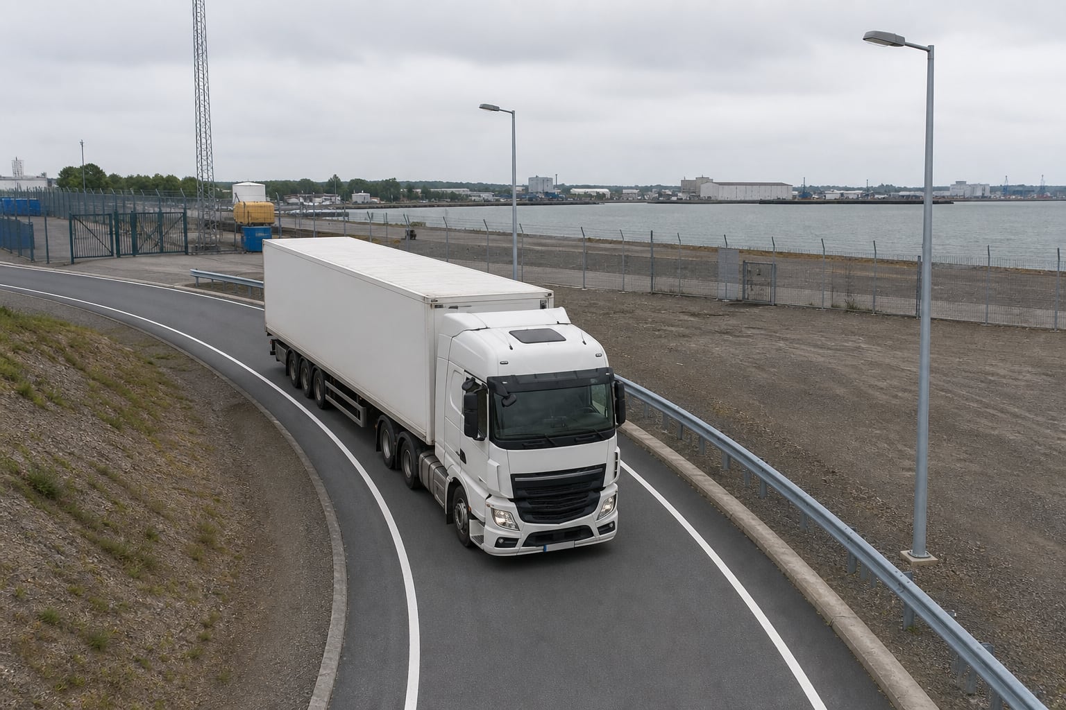
Confirm the pole setback against real vehicle movement and protective works.
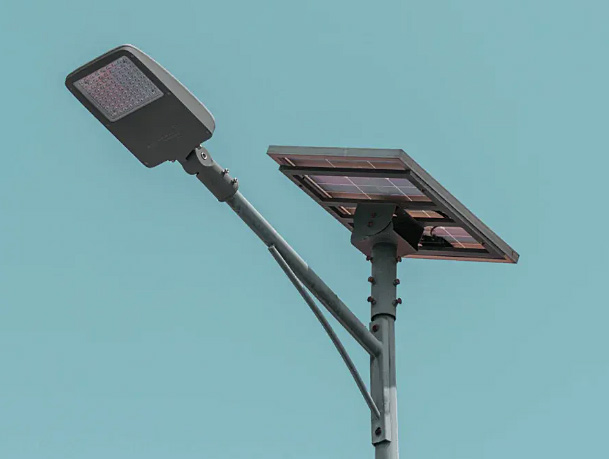
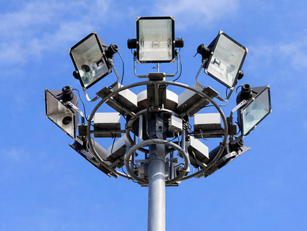
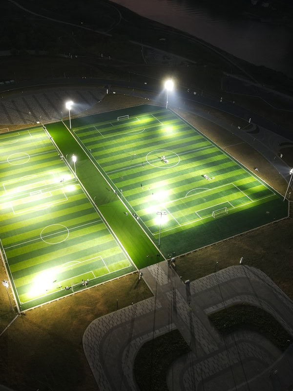
Conventional roadside poles and yard high masts can coexist, but their optics and controls must be tested together. A clean boundary on a drawing does not guarantee a smooth visual transition. Compare spill, glare, vertical tasks and maintenance access at the actual road/yard interface. The street-pole versus high-mast guide explains the system-choice tradeoff.
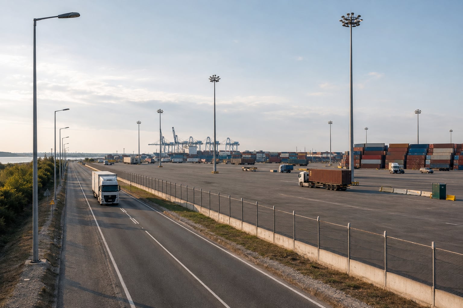
The roadway and yard can use different equipment without losing layout coordination.
Test photometric and structural inputs together
Use the authority or project standard for the required lighting measures and calculation method. Record road geometry, surface assumptions, luminaire file and aiming, maintenance factor and operating state. Study the gate, intersections, pedestrian crossings and other conflict points explicitly. Do not select a universal lux value or spacing from a generic product listing.
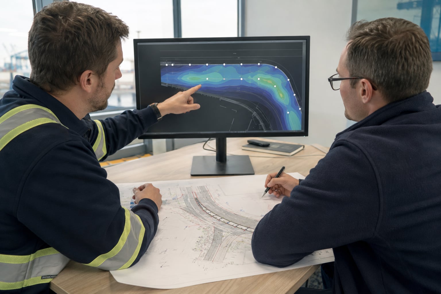
Review the calculation basis alongside the numerical output.
After the luminaire and arm geometry are chosen, send the pole supplier the luminaire mass, projected area, outreach, mounting orientation, permitted attachments and project wind basis. A single-arm road pole and a double-arm median pole serve different configurations; neither should be substituted on nominal height alone.
Detail coastal durability, foundations and maintenance
State the actual exposure and coating system in the RFQ. Salt deposition, standing water, impact and inaccessible interfaces can matter as much as the nominal coating name. Where a duplex system is specified, coordinate galvanizing, compatible organic finish, masked connections, repair procedure and inspection records. See the dedicated coastal duplex-coated pole for that product-level detail.
Place the base above foreseeable ponding where the civil design permits, and resolve anchor pattern, finished levels, cable entry, drainage, door orientation and service clearance on one drawing. The civil designer verifies foundations against site geotechnics and loads; the pole supplier coordinates the base interface. A maintenance plan should show traffic control, safe isolation and access equipment, not simply a nominal inspection interval.
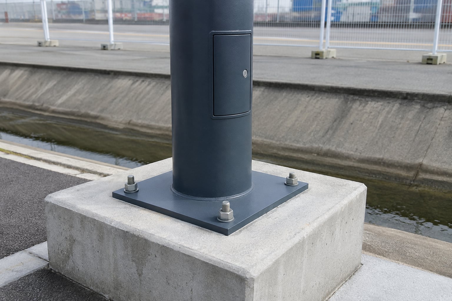
Resolve base elevation, drainage and inspection access together.
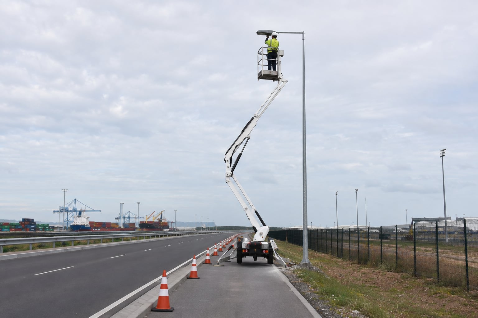
The maintenance method affects pole placement and operational planning.
Issue an RFQ that can be compared fairly
Give bidders the same drawing revision, route schedule, environmental basis, luminaire and attachment schedule, coating requirements, inspection scope and delivery split. Request a compliance statement with clearly identified deviations. The quotation should distinguish pole fabrication and coating from luminaires, foundations, installation and controls where those are by others. This makes commercial comparisons meaningful without implying that the lowest unit price is the lowest installed cost.
Table 2. RFQ evidence and handover checks
| Package item | Submit with RFQ | Check before acceptance |
|---|
| Road and lighting basis | Geometry, criteria, luminaire files and calculation assumptions | Approved layout and photometric revision |
| Pole and wind basis | Pole schedule, arms, loads, EPA and wind inputs | Shop drawings, base interface and calculation references |
| Coastal finish | Exposure description and approved coating specification | Inspection, repair and packing records |
| Construction interface | Foundation levels, cable routes and access plan | As-built coordinates, electrical checks and handover scope |
Use the tender comparison guide for bid normalization and send the project drawings through Jieyao's contact page when a pole quotation is needed.
Frequently asked questions
Can one pole type cover the gate and the whole port road?
Only if the lighting study and structural schedule support that configuration. Gate tasks and internal roads often require different optics, arm direction, setbacks or protection.
Are high masts required beside a port?
No. Large open yards may suit high masts, while narrow road and gate tasks may suit conventional poles. The decision needs actual geometry, photometric results and maintenance access.
What coastal coating should be specified?
Specify the system against the project's exposure and governing requirements. Include surface preparation, interfaces, inspection, repair and packing rather than assuming a generic label establishes durability.
Who designs the pole foundation?
The project civil or structural designer verifies the foundation using site conditions and the engineered pole reactions. The pole supplier provides and coordinates the base and anchor interface.
What should be sent for a comparable quotation?
Send the same current route plan, pole and luminaire schedule, wind/exposure basis, coating specification, foundation interfaces, inspection scope and delivery terms to every bidder.