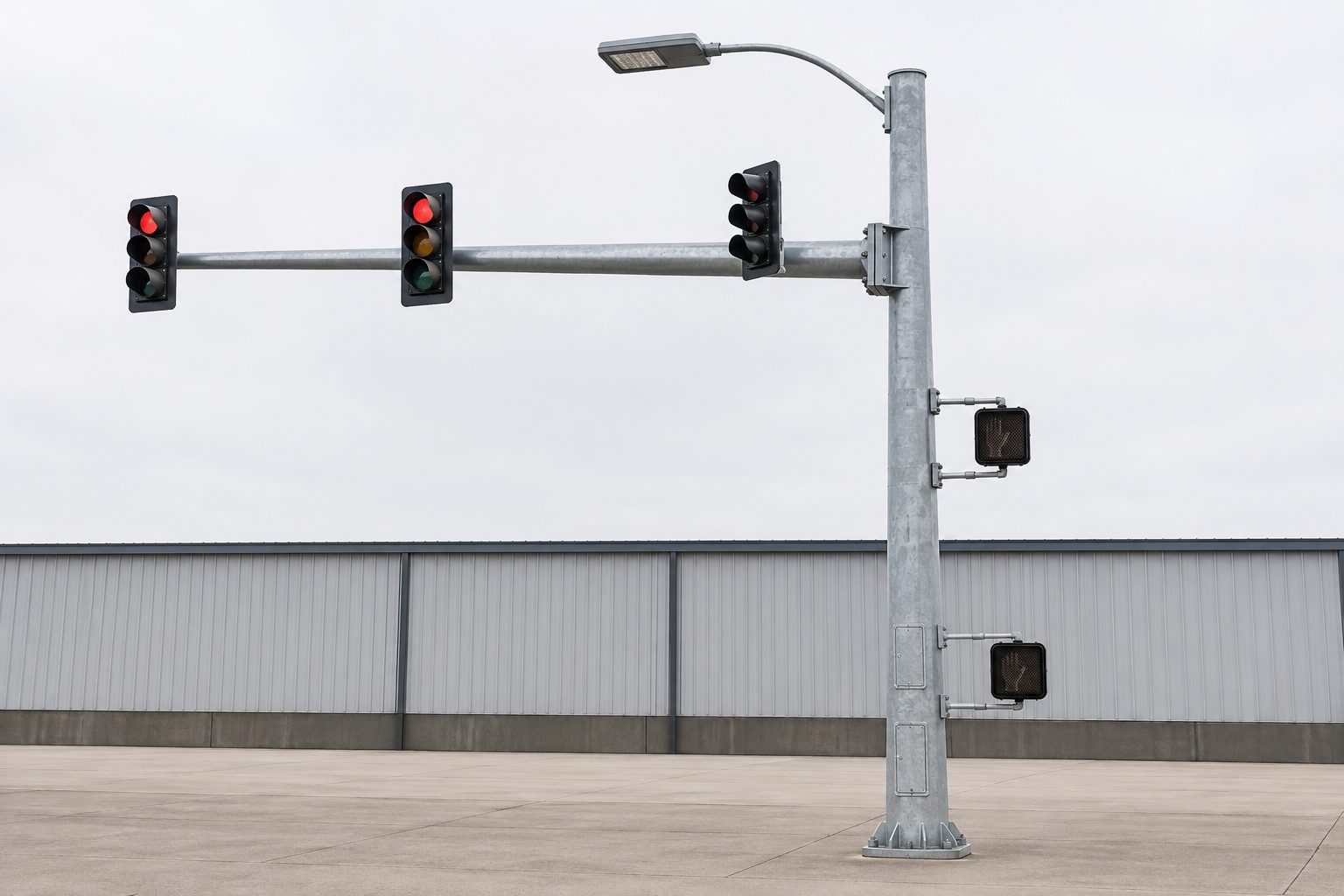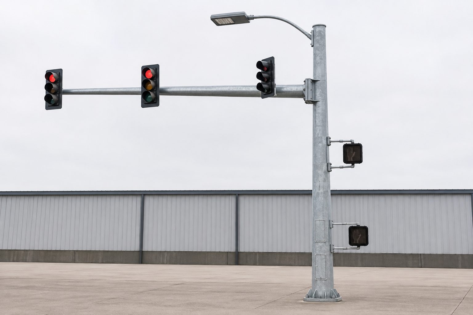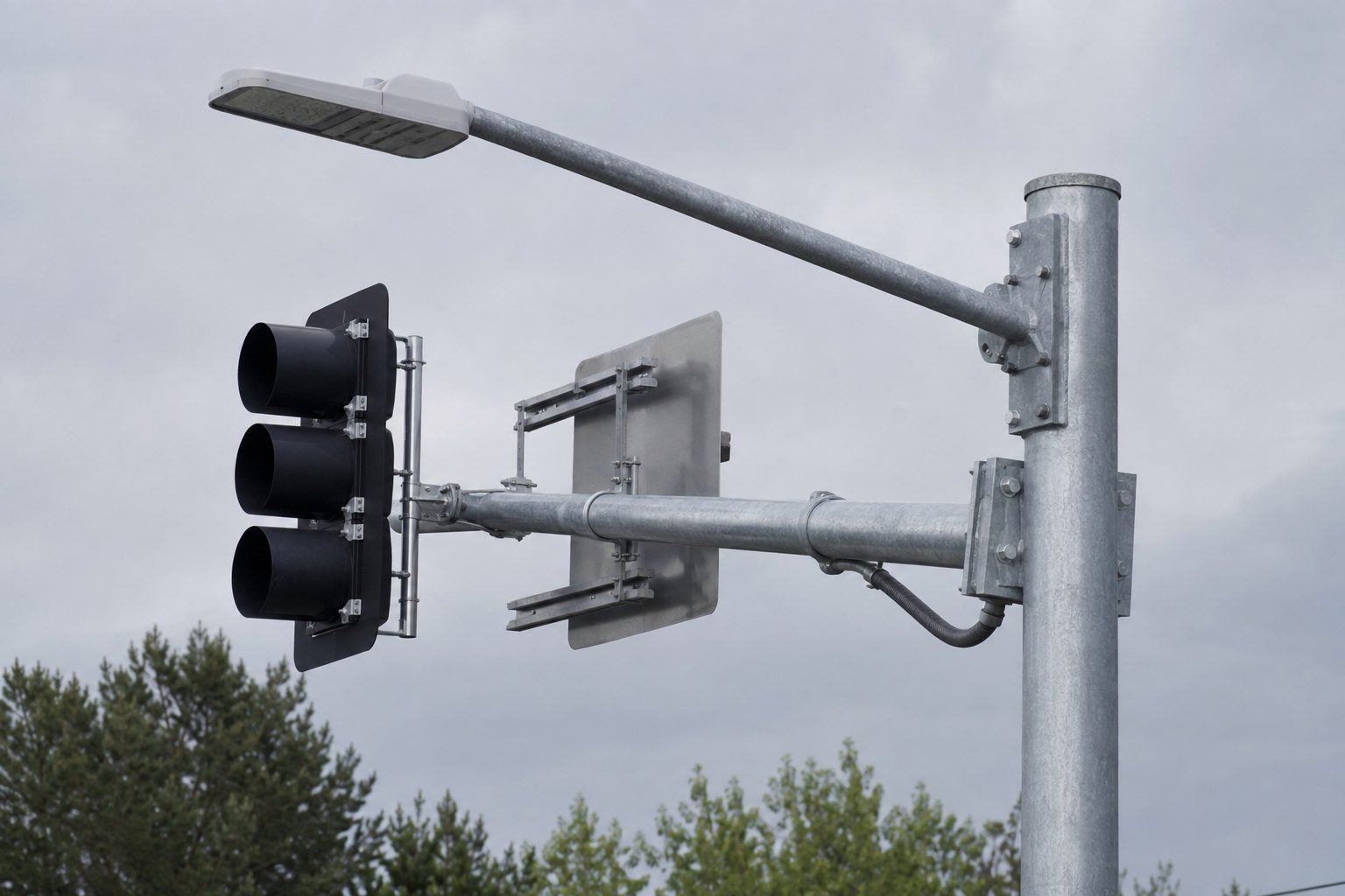


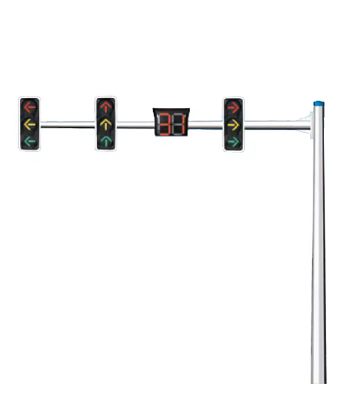
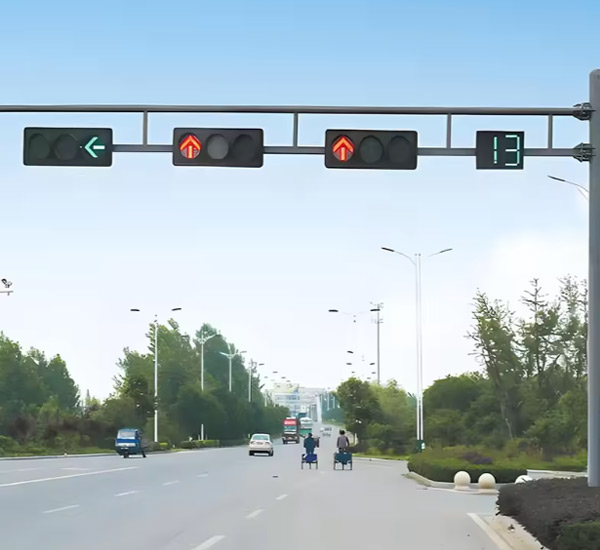
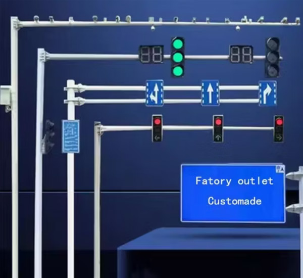
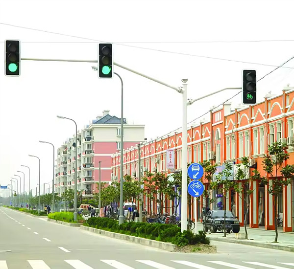
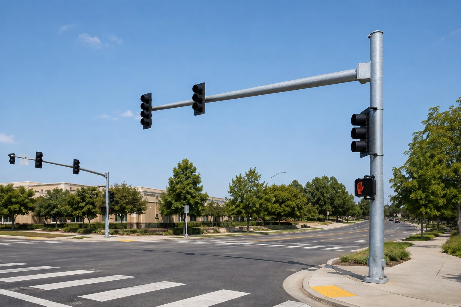
A project-configured galvanized steel structure that coordinates traffic signal heads, roadway lighting, pedestrian indications, signs and selected road equipment on one pole. Mast-arm geometry, equipment loads, cable routes, access chambers, base plates, anchors and drawings are developed around the actual intersection.
A traffic signal and street lighting combination pole is not simply a standard lighting pole with signal heads added later. It is a coordinated roadside structure whose shaft, mast arms, luminaire arm, brackets, access openings and base connection respond to a defined equipment schedule. Signal heads must face the correct approaches, the roadway luminaire must occupy its photometric position, and every cable must reach the intended chamber without interfering with another system.
Jieyao develops the pole from the intersection plan, elevation, attachment schedule and governing design basis. The result may be a single upright with one signal mast arm and one lighting outreach, or a more complex multi-purpose road pole carrying pedestrian indications, signs and approved ancillary equipment. The final arrangement follows reviewed drawings rather than a universal catalogue size.
This page serves buyers looking for a galvanized traffic light pole with street light integration. Broader digital-city equipment belongs to the Smart / Multifunctional Pole range; this product stays focused on the structural and procurement requirements of an intersection signal-and-lighting support.
Combining signal control and roadway illumination can reduce competing foundations around crowded corners where sidewalks, utilities, drainage and accessibility routes all need space.
Factory, port and logistics entrances can coordinate vehicle signals, directional signs and lighting on a robust galvanized support designed from truck-route geometry.
Ramp terminals and arterial approaches may require long signal arms, clear lane control and a separate luminaire position within a demanding wind exposure.
A coordinated pole can simplify streetscape appearance when signal heads, pedestrian equipment and street lighting must share a consistent finish.
| Item | Project Direction | Required Input |
|---|---|---|
| Pole arrangement | Signal mast arm plus roadway-lighting arm | Intersection plan, approach direction and equipment locations |
| Nominal height | Defined by signal and luminaire mounting levels | State each vertical reference, not height alone |
| Signal arm reach | Custom span, rise and connection | Lane centers, signal positions and clearance envelope |
| Lighting arm | Straight, swept or approved outreach form | Outreach, rise, tilt and luminaire tenon |
| Equipment | Signals, pedestrian indications, signs and approved devices | Weight, dimensions, EPA, bracket and cable details |
| Steel system | Project-selected grade and wall schedule | Material standard and structural criteria |
| Shaft form | Tapered polygonal or approved geometry | Transport, access opening and appearance requirements |
| Surface protection | Hot-dip galvanizing; compatible duplex coating if specified | Environment, standard, color and acceptance method |
| Base and anchors | Flanged base with project-matched anchor cage | Reactions, bolt circle, projection and conduit plan |
| Documentation | Arrangement, fabrication and packing documents | Submittal stages and approval responsibilities |
The table describes configurable directions, not universal dimensions or ratings. Supply follows the approved project drawing and purchase specification.
Separate traffic signal and street-light poles can simplify individual scopes, but they require more foundations, more underground interfaces and more space near the curb. A combination traffic signal pole can reduce physical clutter and coordinate the visible streetscape. The tradeoff is that the combined structure carries more equipment, more eccentric load and a more complicated internal wiring arrangement.
The choice should be made at system level. The design team should compare foundation count, utility conflicts, maintenance access, spare parts, erection sequence, future expansion and responsibility for signal versus lighting circuits. Combining functions is useful when the integration is planned; it should not be treated as permission to attach unlisted equipment after fabrication.
Signal heads need to align with the controlled lanes and remain within the clearance envelope defined by the road authority. The purchaser should provide a plan with lane centerlines, stop line, pole offset, arm orientation and the intended location of each primary and secondary head. Elevations should identify mounting heights and any vertical separation between signals, signs and the lighting arm.
Bracket positions are easier to verify before steel is cut. A device schedule should identify the bracket type, connection hole pattern, cable exit and adjustment range for every signal head. If final traffic equipment is supplied by another party, interface drawings or physical samples may be needed to avoid site drilling and improvised adapters.
The street-light portion must follow the lighting calculation, not only the visual balance of the pole. Pole setback, luminaire mounting height, outreach, tilt and rotation affect the distribution on the carriageway, crosswalk and conflict zone. The lighting designer should provide the fixture model or at least its photometric and mounting data.
A long lighting arm changes both the light position and the structural lever arm. The optical and structural proposals therefore need a shared geometry. Jieyao can coordinate the mounting tenon, arm rise and cable path after the required luminaire position is known. Conventional roadway-lighting projects without signal equipment can use a dedicated single-arm street-light pole or double-arm street-light pole.
The signal mast arm behaves as a cantilever carrying devices at several positions. Vertical weight creates bending, while wind on signal heads, signs and the arm adds lateral action and torsion. A longer reach can produce much higher demand at the arm-to-shaft connection even when the attached devices appear modest.
Arm diameter, wall schedule, taper, connection geometry and local reinforcement work together. The shaft then transfers these actions through its base plate and anchors into the foundation. Specifying a pole only by height and arm length does not define this load path; the equipment inventory and design method are essential procurement inputs.
Effective projected area, commonly shortened to EPA, helps describe wind exposure from attachments. For a traffic signal mast arm pole, the complete inventory can include multiple signal heads, backplates, pedestrian indications, signs, lighting fixtures, cameras or approved devices. Their areas, shapes, heights and offsets all influence the response.
The inquiry should state the governing standard, wind speed and its definition, terrain or exposure, topography and any importance requirement. A context-free wind-speed claim is not a design basis. Buyers can use the wind-load and EPA RFQ checklist to organize inputs even though the final calculation method may differ between high-mast and intersection structures.
A clear equipment schedule is more useful than a general request for a “multi-function” pole. For each item, list description, quantity, manufacturer or interface, mass, projected dimensions, mounting height, offset, bracket, cable route and whether future capacity must be reserved. Mark which items are supplied by Jieyao and which are free-issued or installed locally.
The schedule becomes the bridge between traffic, lighting, structural and electrical disciplines. It also helps bidders price the same scope. Without it, quotations may assume different signs, signal heads or fixtures and appear comparable when they are not.
The steel grade is selected within the project’s material standard and structural approach. Grades such as Q235B or Q355 may be considered for suitable designs, while equivalent systems require review of documented properties. Higher yield strength does not eliminate checks at openings, welds, connections, base plates or local slender elements.
A tapered polygonal shaft places more section capacity near the base and provides repeatable faces for equipment orientation. The drawing should define top and bottom dimensions, taper, thickness schedule, seam location and straightness. Large openings or clustered cable exits must be integrated into the design rather than cut into a finished standard pole.
Signal arms may use a project-designed flange, sleeve or another approved connection. The detail needs to transfer bending and torsion while allowing practical transport and erection. Bolt access, installation orientation, drainage and galvanizing behavior all matter. Lighting arms require their own connection and luminaire tenon details.
Connection drawings should identify bolt grade, quantity, tightening method, plate geometry and any alignment features. Trial assembly can confirm fit and orientation before packing. Site welding should be avoided unless it is specifically engineered and an approved coating-repair procedure is available.
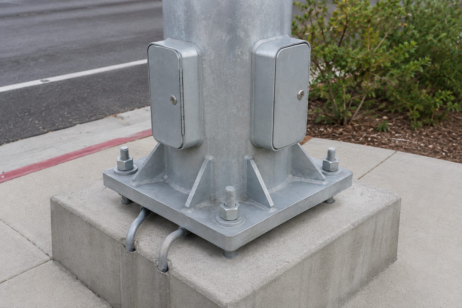
A combined pole may contain signal, lighting and communications circuits with different ownership and maintenance practices. Separate ducts or organized internal routes can reduce congestion and help technicians identify the correct system. The base entry plan should match underground conduits, while internal openings should have smooth edges and protected transitions.
Access chambers must be large enough for the intended terminations and positioned where technicians can work safely. Doors, covers and fasteners should be secure, weather-conscious and compatible with the corrosion-protection system. Compartment size and orientation must be agreed before structural drawings are released because openings affect the shaft.
The project electrical designer should define protective earthing, bonding points, conductor sizes, surge-protection approach and separation requirements. The pole can include welded or bolted earthing provisions at agreed locations, but responsibility for field connections and system testing must be clear.
Metal doors, removable arms and equipment brackets may require bonding according to the project rules. Cable pulling also needs consideration: internal bends, arm transitions and exit holes should not damage insulation. Pole drawings should coordinate with controller-cabinet and underground conduit drawings so that circuits do not end at an inaccessible or congested location.
The base plate distributes shaft forces into the anchor group and foundation. Plate diameter or width, thickness, bolt circle, stiffeners, grout space and anchor projection must suit the calculated reactions and installation method. Anchor bolts are not selected only by pole height; combined moment, shear, tension, embedment and concrete design all contribute.
Jieyao can provide the pole base and compatible anchor-cage arrangement with interface information. Foundation dimensions and reinforcement should be verified by the responsible civil engineer using confirmed soil conditions and local rules. For replacement projects, existing anchors should be surveyed rather than assumed from an old drawing.
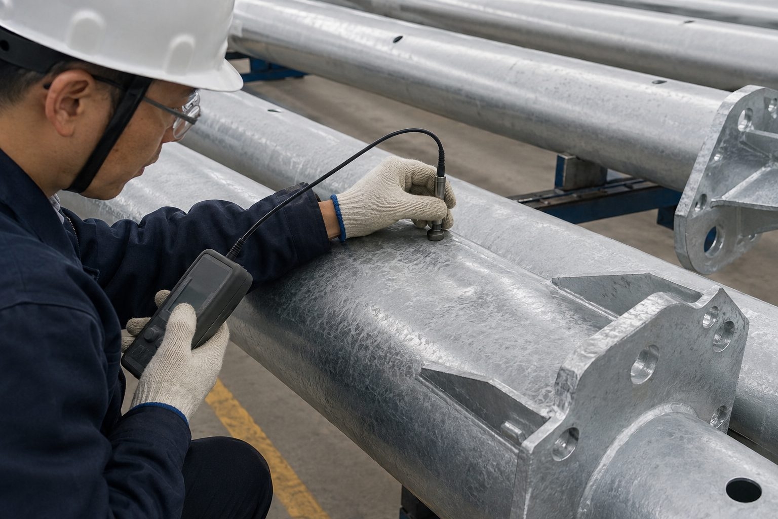
Hot-dip galvanizing protects accessible steel surfaces by forming a bonded zinc coating after fabrication. Vent and drain holes, sealed spaces, overlapping plates and threaded details must be considered before immersion. The purchase specification should identify the referenced coating standard and any inspection requirements.
An additional compatible coating can provide color or a duplex system where the streetscape requires it. Color name alone is not enough: pretreatment, material compatibility, repair method, gloss and acceptance criteria should be defined. For a practical introduction to corrosion protection, see what a galvanized street-light pole is.
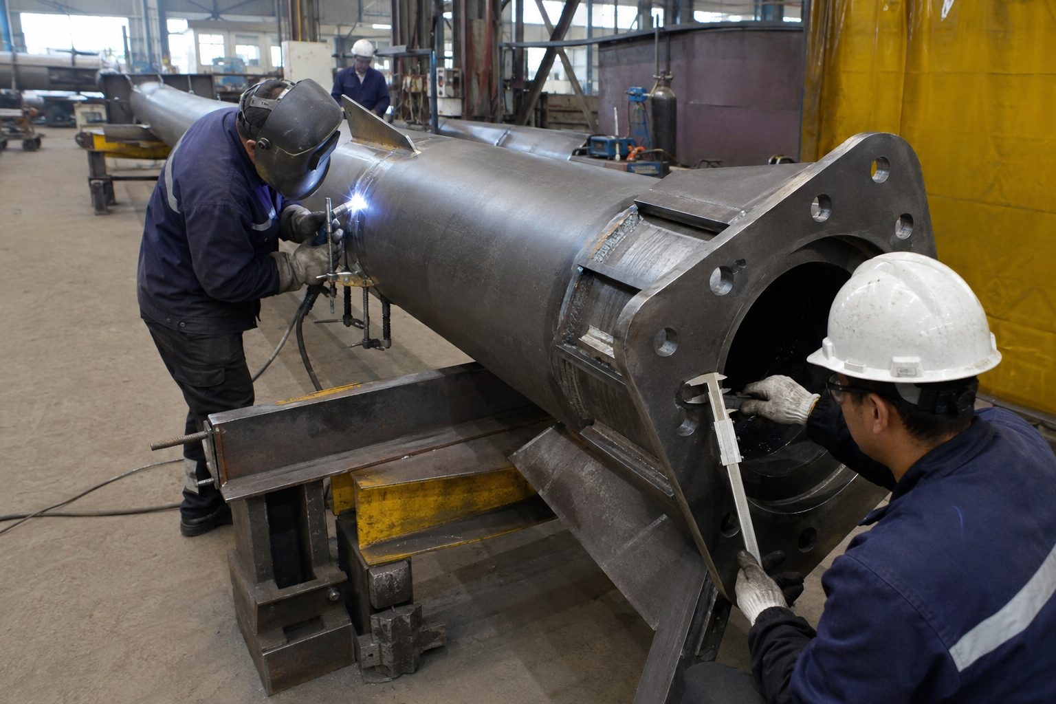
Fabrication begins from approved drawings and identified materials. Plate is cut, formed and welded into the tapered shaft and arms; flanges, stiffeners, service-opening frames and internal provisions are then added in the planned sequence. Critical orientation marks should remain traceable through coating and assembly.
Weld details and inspection scope follow the agreed specification. The fabricator must control fit-up, heat input, distortion and access for subsequent galvanizing. Smooth cable paths and closed edges are checked alongside structural dimensions because a pole can be geometrically correct yet difficult to wire in the field.
After galvanizing, inspection can cover visual condition, coverage, agreed coating measurements and the usability of threads, doors and connection faces. Runs, sharp deposits or interference at fitted interfaces should be addressed using the applicable acceptance and repair method.
Color variation and surface texture can occur in a metallurgical zinc coating and should be evaluated against the specified standard rather than a painted-surface expectation. Where a decorative topcoat is required, preparation and coating application follow the approved duplex system.
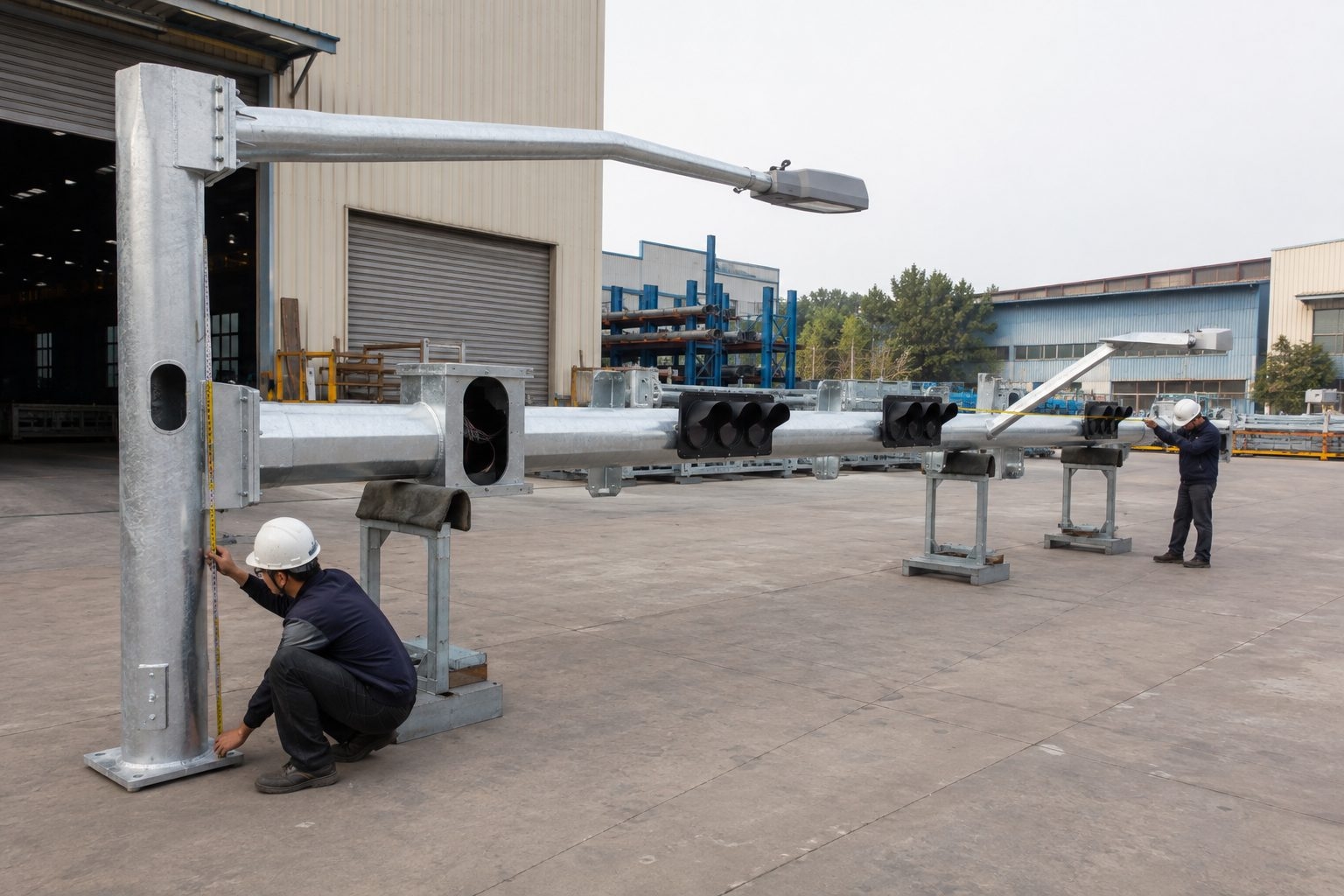
A trial fit can confirm mast-arm connection, lighting-arm orientation, bracket positions and access to bolts. It is especially valuable when several approaches use mirrored or rotated pole arrangements. Identification marks must correspond to the erection drawings and packing list.
Actual signal heads or luminaires are not always present during trial assembly, so interface verification may rely on approved drawings, gauges or sample brackets. Any discrepancy should be resolved before shipment because modifying coated structural components at a busy intersection is costly and disruptive.
The general arrangement should show pole orientation, shaft dimensions, arm reaches, mounting heights, equipment references, doors, cable exits, base plate and anchor layout. Detail drawings cover connections and brackets. A drawing register helps both parties track submitted, commented and approved revisions.
Production should use a clearly identified approved revision. Late changes to a signal-head position, sign size or luminaire can affect the structural model and cable path, so they require controlled review rather than an informal note. Procurement schedules should include realistic time for interdisciplinary drawing approval.
| Interface | Confirm Before Order | Typical Evidence |
|---|---|---|
| Traffic equipment | Who supplies heads, brackets and cables | Equipment schedule and interface drawings |
| Lighting equipment | Fixture model, tenon and aiming | Datasheet and photometric layout |
| Civil work | Foundation designer and conduit entries | Reactions and foundation drawing |
| Electrical work | Circuit separation, termination and earthing | Single-line and cable schedule |
| Installation | Lifting, traffic control and bolt tightening | Method statement and inspection record |
Intersection installation requires an approved traffic-management plan, suitable lifting equipment and a clear sequence. Anchor positions, projections, conduit entries and foundation level should be surveyed before the pole arrives. Components are assembled in a controlled area where practical, with protective measures that avoid damaging the finish.
The erection team should follow the approved lifting points and connection procedure. Pole orientation is checked against the approach drawing before final tightening. Signal and lighting equipment is then connected and aimed by qualified personnel, followed by earthing, electrical, functional and alignment checks required by the project.
Work near live lanes creates risks beyond ordinary pole erection. The contractor should plan lane closures, exclusion zones, lifting radii, overhead and underground services, pedestrian diversion and night visibility. These controls belong to the site method statement and local authority process.
Delivery timing should match the closure window because long mast arms can be difficult to store near traffic. Packaging IDs and erection drawings help crews select the correct approach pole without opening every bundle. A pre-installation meeting can align civil, electrical, signal and lifting teams.
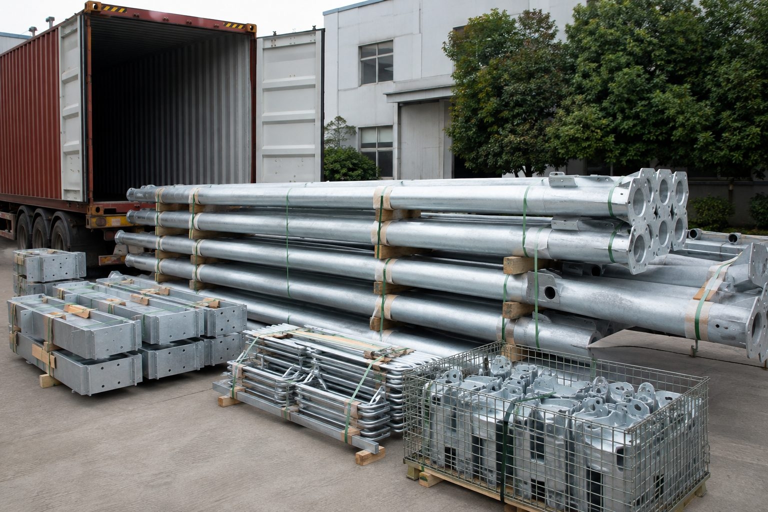
Traffic poles contain many matched parts. Durable identification should connect shafts, arms, brackets, base hardware and anchor cages to the drawing and intersection approach. Packing lists can group components by location or erection sequence where agreed.
Contact points, flanges, threads, doors and projecting brackets need protection against transport damage. Bundle dimensions and lifting provisions must suit container loading and inland handling. The buyer should state any port, container, weight or unloading limits early enough to influence sectioning and packing.
Routine inspection should consider base condition, anchors, access doors, visible coating damage, drainage, arm connections, brackets, cable protection and equipment alignment. The maintenance plan and interval follow the owner’s environment, specification and operating practice.
Future cameras, signs, antennas or larger signal heads should not be installed solely because space appears available. Added attachments change EPA, weight, torsion and cable demand. If future equipment is reasonably known, include it in the original load schedule and reserve compatible interfaces on the approved drawing.
Pedestrian signal heads, push-button stations and audible devices occupy a lower part of the pole than overhead traffic equipment. Their positions must satisfy the authority's accessibility and visibility rules while remaining clear of the service doors, vehicle overhang and maintenance access. A plan view alone is usually insufficient; the elevation should show mounting levels, orientation and the path from each device to its cable compartment.
Crosswalk lighting also needs coordination with the roadway luminaire. The photometric designer may use the shared luminaire, a separate fixture or another lighting strategy depending on the road and applicable criteria. The pole supplier should receive the selected arrangement rather than assume that adding a light above the signal automatically produces the required pedestrian illumination.
Where push buttons or accessible pedestrian signals are installed on the same shaft, mounting plates and internal cable protection should be incorporated before galvanizing. This produces a cleaner interface than field-drilled holes and allows the structural effect of openings to be reviewed. Device ownership, field wiring and commissioning remain clearly allocated in the responsibility matrix.
Road-name signs and lane-use signs can create substantial wind area, particularly when they are mounted far from the shaft. Their overall dimensions, thickness, bracket spacing and location must appear in the equipment schedule. A generic description such as “one sign” cannot support reliable structural comparison because a compact street-name blade and a large lane-control panel impose very different loads.
Cameras or detection equipment should be identified by model or envelope, weight and bracket geometry. The designer also needs to know whether the device must maintain a precise viewing direction, whether its cable requires a separate route and whether maintenance access is available without disturbing signal operation. Equipment should be placed where it does not obstruct signal visibility or conflict with the lighting arm.
A traffic signal and street lighting combination pole can reserve agreed attachment points for these devices, but it should not become an undefined platform for unlimited accessories. Declaring the complete initial and future inventory is the most reliable way to coordinate strength, serviceability, cable capacity and bracket interfaces.
Strength is only one part of satisfactory behavior. The mast arm must maintain required clearance over the road, and movement should remain compatible with signal visibility, fixture aiming and connection performance. The governing specification may define serviceability or fatigue-related checks in addition to ultimate structural resistance.
Clearance should be reviewed for the installed geometry, including arm slope, connection tolerance, foundation level and any expected movement under the specified condition. Simply placing the signal head at a nominal drawing height without considering the full assembly can reduce the available margin. Surveyed road levels are particularly important where crossfall, superelevation or reconstruction affects the vertical reference.
Long arms are more sensitive to stiffness and dynamic behavior. The appropriate checks depend on the governing standard, equipment configuration and site exposure. Jieyao uses the agreed inputs to prepare the proposed steelwork; the purchaser and responsible engineer review the submittal against project-specific clearance and serviceability requirements.
An intersection may contain four poles that look similar in a schedule but use different arm directions, signal positions or door orientations. A configuration code for each approach helps keep design, manufacture, packing and erection aligned. The code should appear on the general arrangement, component marks and packing list.
Orientation can be defined from a consistent reference such as the direction of the signal arm viewed from the base, a north arrow or a station-and-offset system. Doors, cable exits, luminaire arms and secondary brackets are then dimensioned from that reference. This avoids ambiguous labels such as left hand or right hand, which can change depending on the observer's viewpoint.
For repeated junctions, a type code may be combined with a location code. Standardized types reduce drawing volume, while the location code still identifies the correct delivery bundle and anchor cage. Any mirrored arrangement should be explicitly shown; it should not be left to installers to reverse brackets on site.
Before dispatch, the commercial schedule, latest approved drawings, component list and packing plan should agree. Quantities need to include each shaft, signal arm, lighting arm, flange set, fastener set, bracket, door, anchor cage and separately supplied accessory. Spare hardware or touch-up materials are listed independently so they are not confused with installed quantities.
Inspection records are assembled according to the purchase order. Depending on the agreed scope, these may include material traceability, dimensional results, coating records, weld inspection documentation, trial-fit evidence and packing photographs. The exact document set should be defined at quotation stage; it cannot be assumed from a general request for certificates.
This final cross-check is especially useful for an export traffic signal mast arm pole shipment, where a missing matched bracket can delay commissioning after the containers have travelled long distances. Clear marks and a location-based packing list allow the receiving team to verify the shipment before the road closure and crane are scheduled.
A complete RFQ makes technical comparison faster and reduces allowances hidden inside quotations. If some inputs are not yet fixed, mark them as pending and identify who will close them. Jieyao can then separate confirmed scope from assumptions requiring approval.
Compare the proposed equipment inventory, geometry, steel grade, thickness schedule, connection type, finish, anchors, documentation, inspection and packing—not price alone. One quotation may exclude brackets or anchors, use a different wind basis, or assume smaller signs and fixtures. These differences can materially affect both cost and suitability.
Ask each bidder to list deviations and assumptions against the same schedule. Confirm whether calculations are included, which drawings require approval, what inspection records will be supplied and how matched parts will be identified. A technically aligned comparison reduces change orders after the purchase decision.
Height does not define arm reach, attachment loads, wind basis, cable chambers or the foundation interface.
Signal dimensions, backplates, signs and luminaires must be included in the load and bracket schedule.
Changing a fixture, arm position or conduit route after approval can affect structure, fabrication and delivery.
Drilling or welding finished poles can damage protection and alter a reviewed structural detail.
This product is intended for intersections where traffic-control equipment and roadway lighting share one engineered structure. For a conventional signal-only arrangement, use the dedicated traffic-signal pole range. For a general roadway shaft without traffic signals, compare the broader street-light pole range or the 12m highway street-light pole.
Projects centered on connected sensors, displays, communications and city-data platforms should start with the Smart / Multifunctional Pole category. Keeping these intents separate makes each product easier to specify and helps purchasers reach the page that matches their actual scope. More industrial and transport-area solutions are available under Industrial & Special Lighting.
It can coordinate traffic signals, a roadway luminaire, pedestrian indications, signs and agreed road equipment on one structure.
Yes. Reach, rise and connection are configured from lane geometry, clearance, loads and transport limits.
Yes, when interface drawings, weights, dimensions, cable exits and bracket requirements are provided.
Supply scope is project-specific. State whether the luminaire is required or only its pole interface.
Separate or organized routes can be provided when circuit ownership and conduit requirements are defined.
Hot-dip galvanizing is available, with an optional compatible color coating when specified.
Compatible anchor cages can be included after the base interface and foundation responsibilities are agreed.
Provide the governing standard, wind speed definition, exposure, topography and complete attachment schedule.
Yes, if the future weight, EPA, position and interfaces are included in the approved design basis.
Agreed arrangement and detail drawings can be submitted for review before production.
Trial fitting can be arranged for agreed connections and brackets before packing.
Send the intersection drawings, equipment schedule, wind basis, finish, quantities and destination.
Send Jieyao the intersection layout, equipment schedule, wind basis, finish, quantity and delivery destination. We can review the structural, equipment, electrical and civil interfaces before preparing the proposed drawing and quotation scope.
Contact Jieyao
Industrial lighting is designed for extreme environments, featuring higher IP ratings, superior heat dissipation, impact resistance (IK ratings), and extended lifespans under high heat, dust, or humidity.
Named for its saucer-like shape, the UFO High Bay offers a compact design, high heat dissipation efficiency, easy installation, and a modern look, making it a popular choice for warehouses and factories.
Our specialized industrial lights can operate stably in high-temperature environments up to 65°C, suitable for steel mills or boiler rooms.
Yes — we supply industrial-grade explosion-proof lights built for hazardous and high-risk environments. These lights are designed to keep your facility safe while providing reliable, bright illumination.
Glare causes eye fatigue and can lead to accidents. Our anti-glare lens design (UGR < 19) protects workers' vision and enhances workplace safety.
IP65 is commonly used for normal road lighting and can handle rain and dust. IP66 offers stronger resistance against heavy rain and water pressure. IP67 and IP68 are used in more demanding environments where water exposure is more serious, such as coastal areas or industrial zones. IP69K provides the highest protection level and is designed to withstand high-pressure, high-temperature washing, often used in extreme industrial conditions.
Stadium lighting emphasizes CRI (>80/90) and flicker-free performance for HD broadcasts, while factory lighting focuses on durability and energy efficiency.
Tri-proof stands for waterproof, dustproof, and anti-corrosive. It is commonly used in parking lots, car washes, tunnels, and chemical plants.
Yes. This system automatically adjusts indoor brightness based on natural light levels from windows, maximizing natural light usage to save on bills.
It is viable for outdoor industrial areas (like storage yards), but for indoor high-power needs, grid power is recommended to ensure 24-hour stability.
Simply provide photos or videos of the failure. After verification, we will ship replacement parts or full units for free via express courier.
Manufacturers provide direct technical support, flexible parameter customization, original spare parts, and more competitive pricing for large projects.
Contact Us
Get a custom lighting solution and quotation for your project. Outdoor lighting manufacturer in Yangzhou, ChinaAbout Jieyao LightingYangzhou Jieyao Lighting Equipment Co., Ltd. is an outdoor lighting manufacturer focused on solar street light systems and high mas... Do you have any questions or requests?
Email: jay@jieyaolighting.com

Click to Chat.
Im online now.