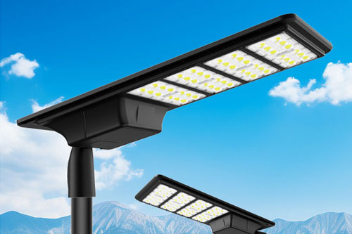


A solar street light installation succeeds when the road-lighting layout, solar energy design, pole structure, civil foundation, electrical connections and controls all describe the same equipment at the same location. The field sequence is straightforward: release the site and drawings, inspect the delivered kit, accept the foundation, erect the pole, fit the PV/luminaire/battery equipment, check the electrical interfaces, demonstrate operation and hand over an as-built record. Do not substitute a generic foundation size, panel angle, battery setting or commissioning duration for the approved design and component manuals. The installer and responsible engineer should resolve discrepancies before a lift or connection is made.
Begin with a location schedule that ties each pole mark to coordinates, mounting height reference, luminaire model, PV module, battery and controller, shaft and arm, base connection and drawing revision. An all-in-one unit and a split system can have different bracket, battery-enclosure and cable-routing interfaces even when the lighting duty appears similar. The specification should identify which party supplies and approves each connection. If the luminaire, battery or panel changes after the structural or energy design was approved, hold that location for a coordinated review.
Survey shading at the proposed module position, not merely at ground level. Check nearby buildings, trees and future obstructions with the project solar-resource method. Record utility locations, traffic management, safe access and available space for the planned lift. Local permit and electrical requirements depend on the project jurisdiction; the installation team should work from the permits and inspection plan actually issued for the site.
| Stage | Review before release | Evidence retained for handover |
|---|---|---|
| Site and location | Pole mark, utilities, access, traffic controls and module-shading assessment agree with the approved layout | Marked layout, survey notes and approved work method |
| Delivery and receiving | Shaft, base, arm, module, luminaire, battery/controller and fasteners match the schedule; shipping damage is identified | Packing comparison, condition photos and serial/mark record |
| Civil interface | Foundation and anchor/embedment details, cable entry, levels and concrete release satisfy the responsible engineer's drawings | Civil inspection and approved release record |
| Erection and assembly | Lift method, pole orientation, bracket fit and coating condition match the drawings and manuals | Lift/assembly checklist, alignment and interface photos |
| Electrical connection | Cable identity, polarity, protection, bonding/earthing and enclosure sealing are checked by qualified personnel | Test results and connection/setting record |
| Commissioning | Controller schedule, charging indication, luminaire aiming, sensor behavior and night operation meet the project criteria | Functional test, as-built settings, defects and acceptance sign-off |
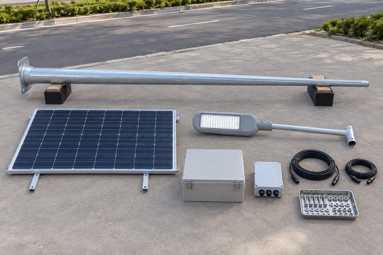
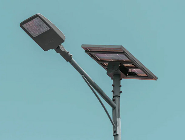
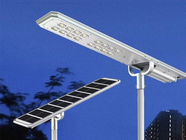
Solar street-light components laid out for a receiving and interface review; confirm actual part identity against the approved pole schedule.
For a split-system configuration, compare the location schedule with the split-type solar street light interface rather than assuming that an all-in-one bracket and cable route are identical.
Check the pole and equipment against the latest approved bill of materials before unpacking everything into a common pile. Keep identity labels with the corresponding location. Look for bent arms, damaged panel glazing, distorted brackets, coating damage, wet enclosures and connector damage. A component that does not fit the controlled drawing should be recorded and reviewed, not field-drilled or rewired merely to keep the programme moving.
The civil team should release the actual foundation interface before pole erection. Confirm the base-plate/anchor pattern or direct-burial detail, projection, level, orientation, cable entry and protection of exposed threads against the approved pole reaction and foundation drawings. The separate foundation and anchor-bolt design guide identifies the information the engineer needs. Soil bearing, concrete strength and curing release are engineering decisions for this site. Neither a nominal pole height nor a generic online table establishes them. If a foundation or anchor cage is out of tolerance, hold the lift and obtain a disposition from the responsible designer.
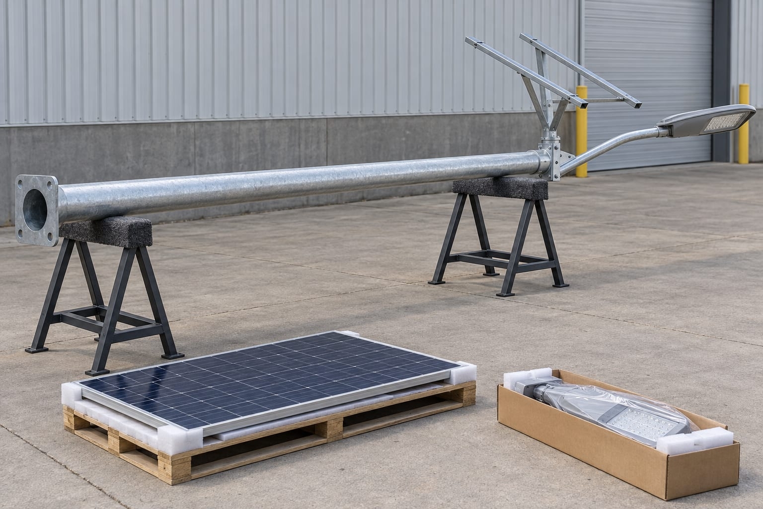
Ground-level dry fit of the pole, luminaire arm and PV bracket before final assembly; this image does not show foundation acceptance.
Use a lift plan, appropriate rigging and an exclusion zone under the local site safety rules. Protect the pole finish, door frame, cable ends and panel mounting surfaces during handling. Orient the access door, arm and module bracket as drawn before final tightening; each may face a different direction for maintenance, road optics and solar access. Pole verticality and bracket alignment are separate checks. Record any site adjustment that affects the approved geometry.
Install the luminaire, PV module and battery/controller enclosure in the sequence required by their manufacturers. Use the specified fasteners and interface details, including cable-edge protection, weather seals, strain relief and the intended service access. Do not assume an IP rating for the entire assembled system from the rating of one component. Panel orientation should reflect the approved energy design and shading survey; luminaire aiming should reflect the photometric design. They are not interchangeable settings.
| Interface | Field check | Stop-work or review trigger |
|---|---|---|
| Pole base and shaft | Mark, orientation, seating, fasteners, coating and accessible cable route | Anchor mismatch, damaged shaft or unapproved opening |
| PV module and bracket | Compatible hole pattern, approved angle/orientation, edge clearance and secure cable exit | New bracket or panel geometry not checked in structural/energy design |
| Luminaire and arm | Correct spigot/adapter, mass and aiming range; cable protected at entry | Fixture substitution, looseness or unsupported field-drilled adapter |
| Battery/controller enclosure | Intended location, secure mount, ventilation and service access per manufacturer | Incompatible enclosure, water entry or inaccessible disconnect |
| DC cabling and protection | Identified polarity, connector compatibility, strain relief and specified protection | Mixed connector system, exposed conductor or undocumented wiring change |
| Protective bonding/earthing | Continuity and termination to the approved scheme, tested by competent personnel | Missing provision or result outside the project acceptance criterion |
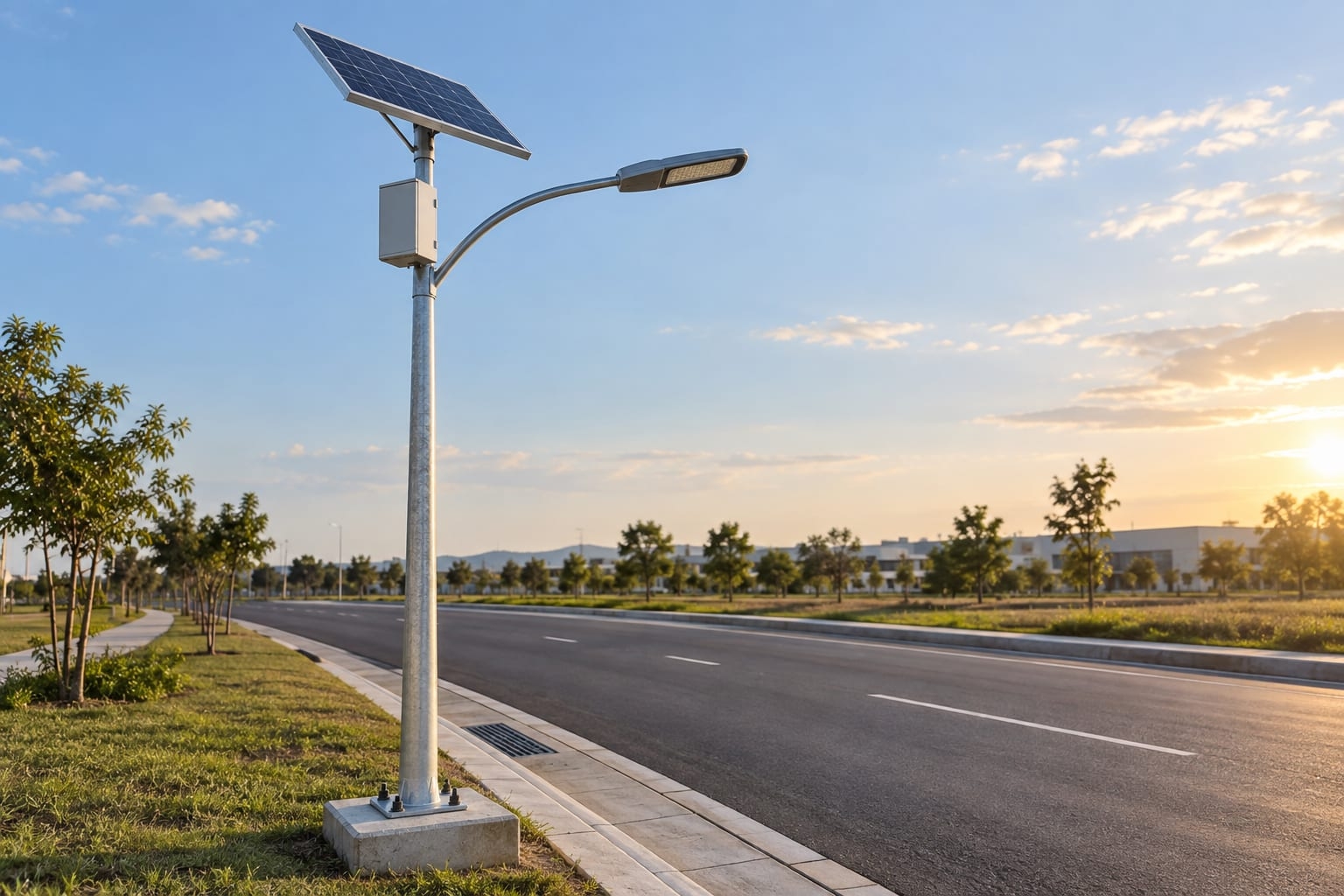
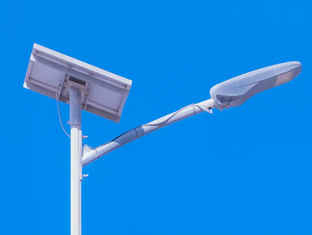
Installed split-type solar street light with a PV module and roadway luminaire on one pole.
Before energizing, a qualified electrical person should inspect connections and apply the tests specified in the approved project and component documents. Record the controller and luminaire identity, firmware/settings where relevant, charging indication, programmed operating profile, sensor behavior and any remote-monitoring configuration in scope. Demonstrate the specified lighting function under suitable conditions, including a controlled night-operation check when required. A daylight charging indication alone is not proof of the project's required night service, and a single night does not establish battery autonomy.
Commissioning criteria must come from the design: luminaire output and aiming, operating schedule, backup/autonomy target, electrical test limits and the required observation period vary by project. If results fail, preserve the measured evidence and diagnose the relevant interface rather than changing settings without recording the revision. Close outstanding defects or document an agreed hold point before handover.
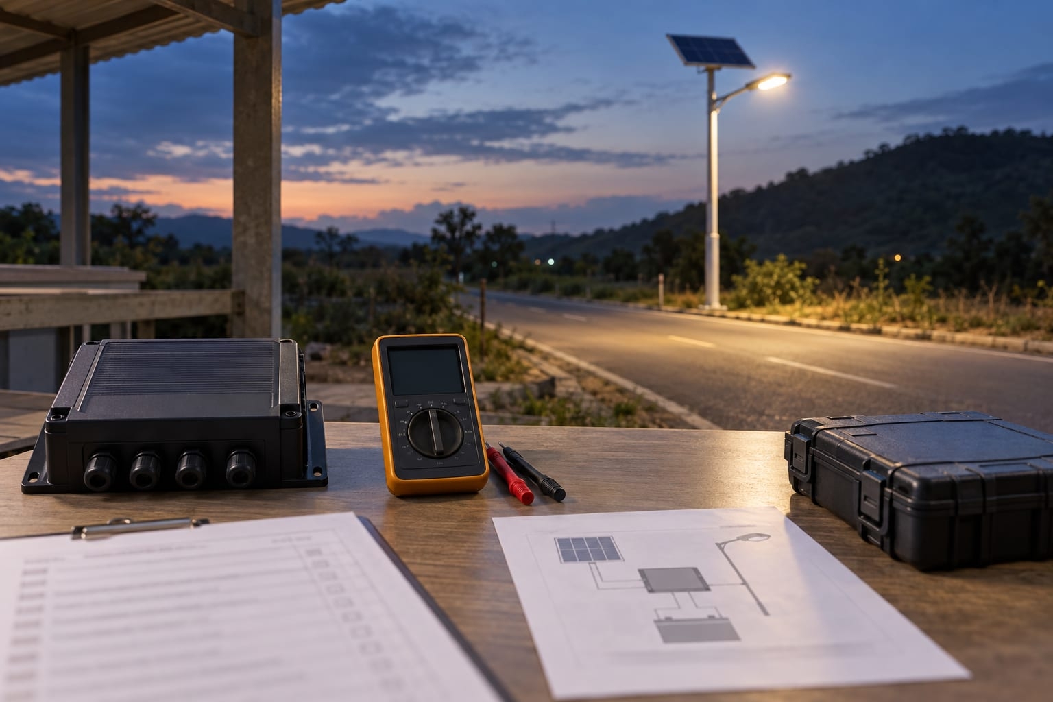
Solar street-light commissioning workspace with a test meter, checklist and wiring drawing.
The owner needs an as-built register by pole mark and location: configuration and serials, drawing revision, foundation/anchor record, electrical and functional tests, controller settings, images, warranties/manuals actually supplied, and open defects with owners and dates. These records make future battery, controller, module and luminaire replacement safer and reduce uncertainty in maintenance; use the pole asset-register and handover guide to structure the record.
For an RFQ or submittal, provide the location schedule, luminaire/optic file, PV/battery/controller data, pole and foundation interfaces, exposure and wind basis, installation responsibilities and acceptance criteria. Jieyao can review a defined equipment-and-pole package against the project information it receives; do not imply that this article replaces a licensed site engineer, local permits or equipment manuals.
Release the site and foundation, match the pole/arm/base to the approved mark, inspect shipping condition and confirm the lift method, rigging, exclusion zone and cable protection. Hold mismatched anchors or damaged parts for disposition.
Not necessarily. PV orientation follows the approved energy design and local shading assessment; luminaire aiming follows the lighting design. The bracket and structural review must accommodate both.
No. The project engineer determines geometry and release criteria from loads, soil, anchors, concrete design and site conditions. Installation should not proceed on a generic web value.
The agreed inspection and test records, approved controller settings, demonstrated required functions, as-built equipment/location register and closed or formally assigned defects—not simply that the light turns on once.
Only after the responsible parties check physical interfaces, electrical compatibility, energy/autonomy duty, mass/EPA and any drawing or acceptance changes. Record the approved substitution against the pole mark.
Contact Us
Get a custom lighting solution and quotation for your project. Outdoor lighting manufacturer in Yangzhou, ChinaAbout Jieyao LightingYangzhou Jieyao Lighting Equipment Co., Ltd. is an outdoor lighting manufacturer focused on solar street light systems and high mas... Do you have any questions or requests?
Email: jay@jieyaolighting.com

Click to Chat.
Im online now.