


Plan industrial park road lighting around truck movement, junctions, loading entrances, staff parking, pedestrian routes, security, controls, maintenance and a reviewable pole procurement package.
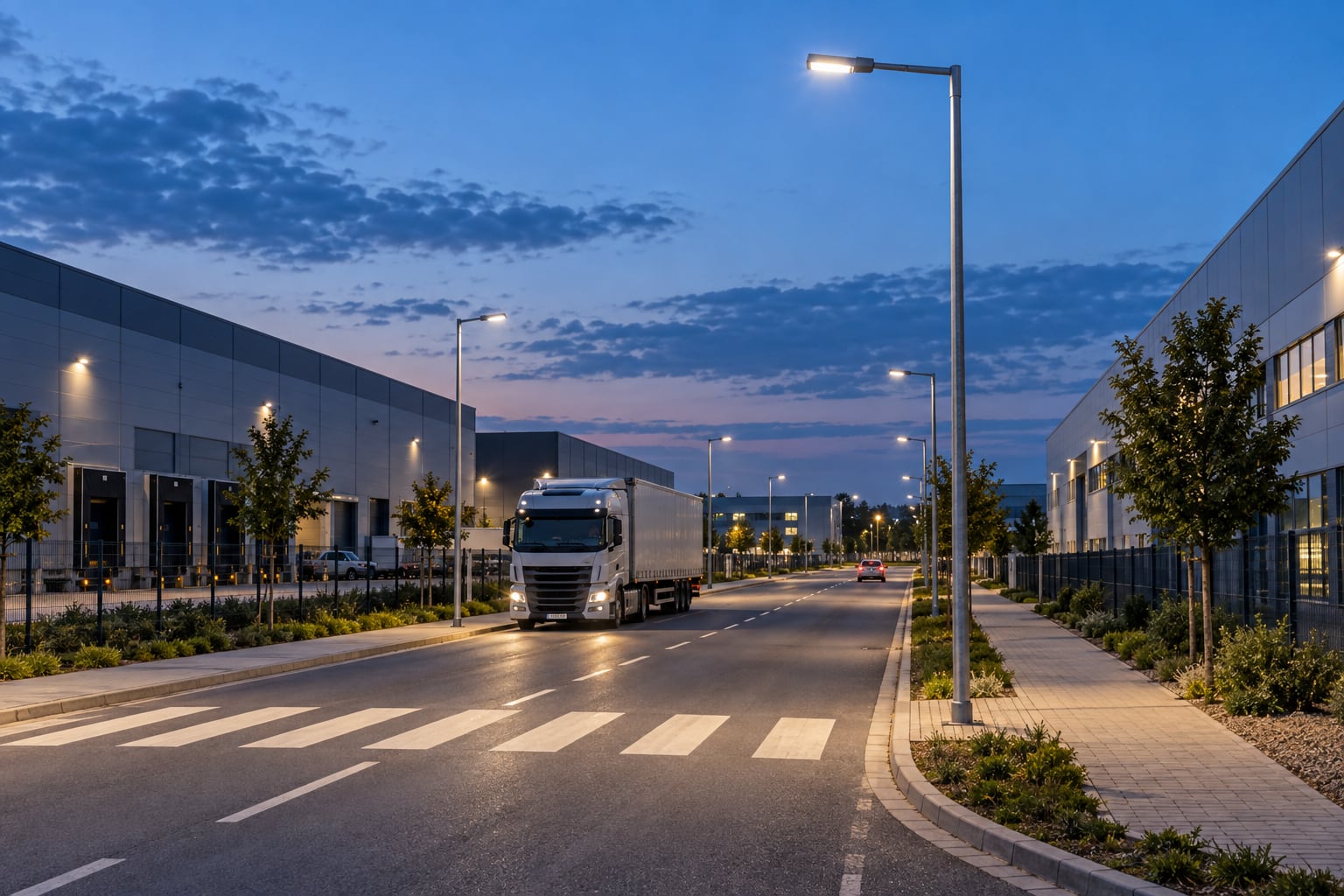
An industrial campus can contain public approaches, controlled gates, heavy-vehicle routes, loading entrances, employee parking, pedestrian paths, utility corridors and emergency access. Each zone has a different visual task, but drivers and workers move between them. Industrial park road lighting should therefore be planned as a connected network rather than as isolated rows of poles.
The process begins with road geometry and operating conditions. Lighting criteria, pole families, luminaires, foundations, circuits and controls then follow. This guide supports the coordination and procurement process; the responsible project designers still select the governing lighting, traffic, structural, electrical and safety requirements for the actual location.
Classify the main approach, primary truck spine, secondary service roads, loading-bay connectors, fire routes, staff access and parking aisles. Record lane count, travel direction, expected vehicle type, operating speed, curb, shoulder, median, crossings, barriers and nearby buildings. The lighting design should reflect how each route is used after dark.
Give each road segment and pole position a stable identifier. A schedule can connect route, lighting criterion, operating hours, pole family, luminaire, control group and construction phase. This structure helps consultants, buyers and suppliers discuss the same equipment without relying on ambiguous names such as “warehouse road.”
The public-road interface may have different authority criteria, speeds, signs and existing lighting. Inside the gate, the owner may control operational standards and schedules. Design the transition intentionally so drivers do not move from a bright entrance into an unexpectedly dark internal route or from a dark perimeter into excessive glare.
Coordinate ownership at the boundary. Confirm who supplies the last public-road pole, entrance fixtures, gate lighting and internal circuits. The physical transition may need compatible mounting heights and optics even when the equipment belongs to different contracts.
Heavy vehicles need wider turns, longer stopping sight distance and more vertical clearance than cars. Map swept paths for the actual tractor-trailer, rigid truck, tanker or specialized vehicle expected on each route. Pole shafts, foundations, cabinets and maintenance positions should remain outside that envelope and should not reduce the usable shoulder.
At curves and junctions, luminaires should reveal road edges, obstacles and directional changes without distracting glare. A repeated pole line can support visual guidance, but spacing follows the photometric result. Protective curbs or barriers must be shown on the civil plan if they form part of the equipment-protection strategy.

Intersections, gate merges, loading-bay approaches and reversing zones contain more visual information than a straight road. Drivers may need to identify pedestrians, barriers, dock numbers, queue positions and vehicles entering from the side. Treat these as conflict zones with a deliberate lighting and glare review.
Lighting equipment should not block sight triangles or occupy trailer swing areas. Where a loading entrance connects directly to a road, separate the linear road task from apron operations. A luminaire intended for a broad yard may produce uncomfortable glare for an approaching driver if its aiming and shielding are not coordinated.
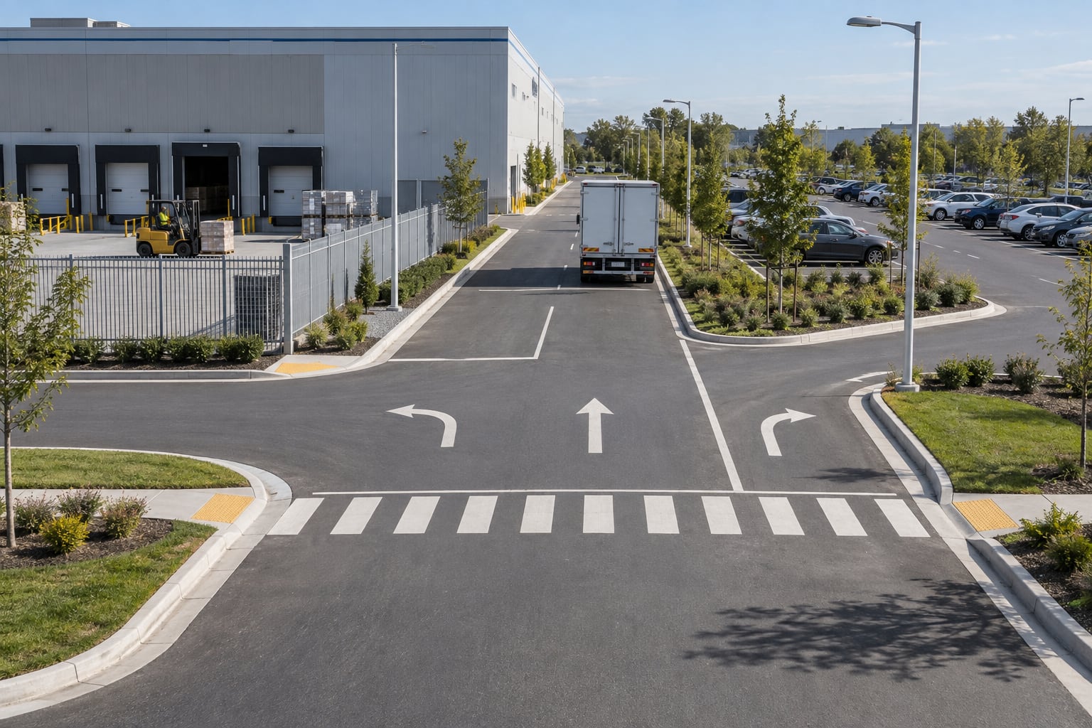
Mark sidewalks, crossings, staff entrances, bus stops, bicycle parking and routes between car parks and buildings. Lighting should help users see path edges, vehicles and changes in level while controlling glare toward eye height. Conflict points need attention where shift changes concentrate many people near truck traffic.
Roadway poles may contribute to walkway lighting, but they should not be assumed to cover every pedestrian task. Lower bollards or building-mounted fixtures can support paths if they remain coordinated with the road system. Emergency routes and accessible paths should retain required visibility under the planned operating schedule.
A security gate combines vehicle identification, barrier arms, lane-control equipment, pedestrians and camera fields. Place poles so they do not create harsh backlight for guards or obscure cameras. Drivers should be able to see the queue, lane edge and stopping point without looking directly into a luminaire.
Gate lighting may remain active when other campus areas dim. Identify it as a separate control group if needed. Foundations, ducts and cabinets should avoid vehicle impact zones and the underground loops or communications serving the gate.
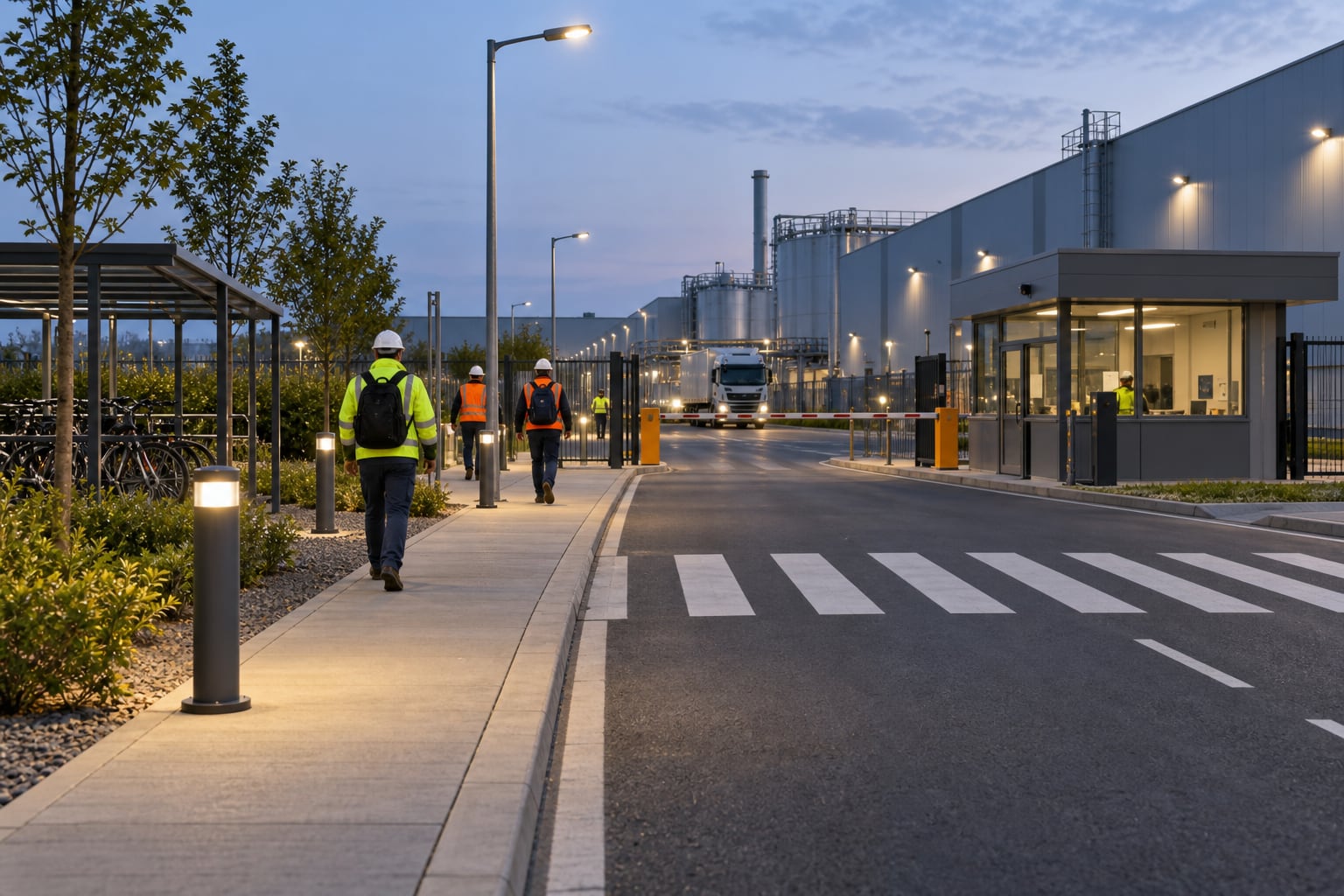
Employee parking is an area-lighting task with slower vehicle movement, frequent pedestrians and many obstructions. Its pole family can differ from the internal road system. A dedicated galvanized parking lot light pole may use twin or multi-directional brackets, while the connecting road uses single-arm roadway poles.
Design the entrance and pedestrian connection as a transition zone. Confirm curb ramps, crossings, barrier gates, bicycle areas and maintenance access. Circuits may follow different schedules, but the route to occupied buildings should remain understandable when a remote parking row is dimmed.
Road luminaires direct light along and across a carriageway. Loading yards require broader area coverage around trailers, docks and maneuvering spaces. One system should not be stretched to perform both tasks without calculation. The boundary may combine roadway poles, twin-fixture area poles, building-mounted lights or high masts.
Check overlapping light, glare and controls at the transition. If the yard circuit is switched off, the road should still remain coherent. If apron luminaires are brighter, approaching drivers should adapt without a sudden visual change that hides road edges or pedestrians.
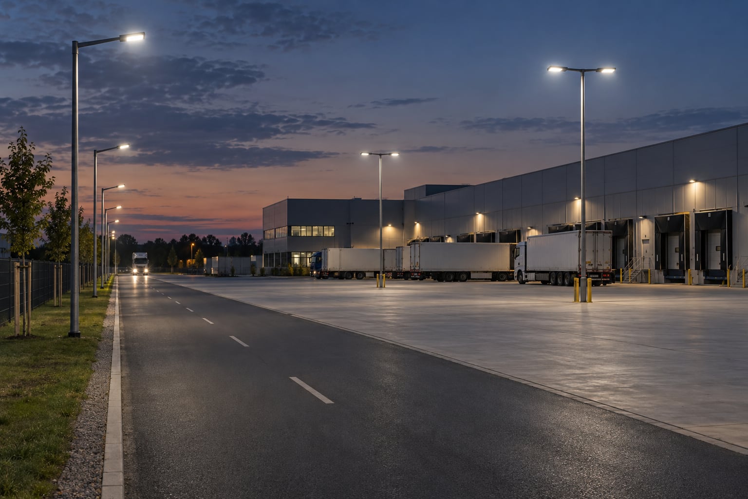
The project should state applicable maintained illuminance, uniformity, glare, vertical-lighting and other criteria for each task. Values depend on local standards, owner policy, risk and operation. A single lux target for the entire campus can over-light quiet roads while leaving junctions or crossings inadequately considered.
Model representative surfaces and calculation grids. Include road lanes, junctions, crossings, walkways, gate areas, loading interfaces and parking. Document maintenance factors and operating scenes so bidders understand whether results describe initial or maintained conditions and which circuits are active.
Mounting height influences coverage, glare, pole count, structural demand and maintenance equipment. Spacing depends on height, luminaire optics, road width, curvature, setbacks and required uniformity. A fixed spacing-to-height rule cannot replace calculation for a mixed industrial site.
Test candidate arrangements in the photometric model and review them with the civil plan. Fewer taller poles may reduce foundations but increase access height and top load. More lower poles may follow a complex route more closely but add ducts, conflict points and maintenance locations.
Provide tested photometric data for the proposed LED luminaire. Select an optical distribution that places useful light on the road without excessive spill toward offices, neighbors, guardhouse windows or drivers. Tilt and outreach change both coverage and glare, so they belong on the approved layout and pole drawing.
High output alone does not prove a suitable design. Compare uniformity, vertical visibility, backlight and installed power across realistic layouts. Shielding may help a boundary condition, but it can also alter distribution and should be included in the calculation.
A single-arm galvanized pole commonly serves a road edge where the luminaire projects over one carriageway. A double-arm pole may suit a median or two adjacent directions. Neither arrangement should be selected solely from appearance.
Arm reach, rise, tilt and luminaire orientation follow the photometric layout. The structural design uses the mass, exposed area and eccentricity of the complete top assembly. Door and arm direction should be unambiguous on site drawings.
Conventional roadway poles suit linear routes and repeated edges. Parking-area poles can serve broad but moderate-scale open areas from single, twin or multi-fixture brackets. A high mast lighting system can cover a much larger apron with fewer locations, but it requires a dedicated headframe, foundation, access strategy and glare review.
Industrial parks often use a combination. Choose each family by target area, obstructions, maintenance access, wind and civil constraints. Do not use a high mast simply to avoid detailed layout work, and do not fill a large yard with roadway poles without comparing whole-site effects.
Show pole coordinates relative to curbs, barriers, loading docks, hydrants, pipe racks, rail spurs, overhead doors and hazardous-process boundaries. A pole that is photometrically convenient may be vulnerable to trailers or interfere with fire access. The project designer determines required protection and setbacks.
Where barriers are used, coordinate their foundation with the pole footing and underground ducts. Protect cabinets and handholes as well. Avoid locating access doors where technicians must stand in an active lane or beneath process equipment.
An industrial road light pole is a structural assembly, not only a mounting height. The engineer needs the governing standard, site wind basis, exposure or terrain, topography, luminaire quantity, bracket geometry and effective projected area (EPA). Cameras, signs, antennas and seasonal attachments must also be declared when they are part of the design.
Give the pole supplier the final fixture data before approving the shaft, base plate and anchors. A late change from one compact luminaire to a longer arm with added equipment can alter structural demand. Request project-specific calculations when the contract requires them, and keep the approved fixture-and-arm schedule linked to the pole mark.
Foundation design depends on reactions, soil information, frost or groundwater conditions, local practice and surrounding utilities. The lighting layout should be checked against storm drains, fire-water lines, process piping, communications ducts and future expansion corridors before foundations are released. A small plan shift made early is usually easier than redesign after excavation.
Set finished levels so water does not pond around the base or enter the access opening. Show conduit entries, earthing provisions, anchor templates and any protective sleeves clearly. The pole manufacturer can supply interface dimensions, while the project civil and structural designers remain responsible for the site foundation. Use the foundation and anchor bolt guide to structure this exchange.
Divide circuits in a way that reflects how the facility operates. Gate roads, security routes, loading approaches, staff parking and secondary service roads may have different operating hours or resilience priorities. Logical circuit boundaries make isolation and fault finding easier without darkening the entire site.
Coordinate voltage, cable route, allowable voltage drop, protective devices, earthing and control interfaces with the electrical design. Provide spare duct capacity where later warehouses or yards are likely. Pole access openings should allow safe termination and maintenance without forcing tight bends or exposing connections to standing water.
Timers, photocells, astronomical clocks, central management and occupancy-based dimming can reduce unnecessary operation. Control zones should follow actual traffic and security patterns. Keep critical junctions, gates and pedestrian conflict points readable when low-activity areas are dimmed.
Define normal level, reduced level, override conditions, recovery time and failure behavior in the controls schedule. Test the sequence at night with operations and security staff. An energy strategy is only successful when drivers and pedestrians still receive a clear visual transition between adjacent zones.
Emergency egress, security surveillance and ordinary roadway lighting are related but not interchangeable. Identify muster routes, emergency vehicle access, guardhouse approaches and camera observation zones. Decide which circuits require backup power or rapid restoration according to the facility risk assessment.
Where cameras share poles, include their weight, projected area, mounting position, cabling and service access in the design. Avoid glare into camera views and guardhouse windows. Keep security equipment below or separate from high-voltage compartments when local rules and the equipment arrangement require it.
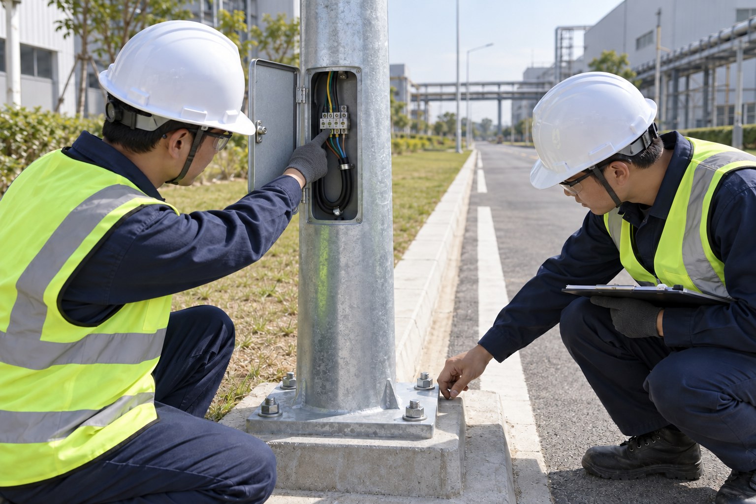
Hot-dip galvanizing is a common baseline for steel poles, but the environment and owner expectations determine whether additional coating is appropriate. Chemical emissions, coastal salt, de-icing salts, standing water and repeated abrasion can change the protection strategy. Describe the exposure rather than asking only for a generic painted pole.
Specify finish system, color, surface preparation, repair method and inspection records in coordinated project documents. Drainage and vent details must remain compatible with fabrication and galvanizing. For aggressive coastal exposure, compare a project-specific duplex system with the relevant maintenance plan instead of relying on appearance alone.
Place poles where a lift truck or service vehicle can stop without blocking a gate, loading lane or emergency route. Check overhead clearances, soft shoulders, medians and turning space. Access doors should face a safe working side and remain clear of barriers, landscaping and stored materials.
Standardize common luminaires, drivers, doors and fasteners where practical. Record pole marks, circuit numbers, fixture types and control addresses. A maintainable scheme reduces fault-finding time and helps the facility replace like-for-like components without losing the approved optical or structural configuration.
Industrial parks are often built in stages while earlier units remain operational. Define the permanent road spine, temporary dead ends, future junctions and interim yard limits. Keep lighting circuits and pole positions useful after later phases connect, and avoid temporary installations that obstruct the permanent drainage or utility corridor.
For each stage, document which routes are open, which pedestrian paths are protected and how dark construction areas are separated. Review control programming after every handover. A phased drawing should show both the current operating condition and the future interfaces so contractors do not remove essential coverage.
Before erection, verify foundation levels, anchor projection, bolt pattern, conduit position and pole identification. Inspect shafts, brackets and finishes for transport damage. Use the approved lifting method and keep workers outside suspended-load zones. Do not pull a base plate into alignment by excessive bolt force.
After erection, check verticality, bracket orientation, fasteners, access doors, earthing and cable termination. Aim adjustable luminaires to the recorded setting, then complete night commissioning with the site in a representative operating state. The street light pole installation guide provides a practical sequence for receiving, erection and handover. Record exceptions and corrections rather than relying on an unmarked visual approval.
The final package should include pole schedules, approved drawings, foundation interfaces, fixture data, circuit information, control settings, inspection reports and as-built coordinates. Link each installed pole mark to its product and maintenance information. Clear records prevent later teams from mixing incompatible arms, doors or luminaires.
Photograph hidden conduit entries and completed bases where the project procedure permits. Retain the final night-test record and any agreed aiming changes. When the park expands, this information gives the designer a reliable starting point instead of forcing a new survey of every existing assembly.
Replacing luminaires can improve efficiency, but it changes weight, EPA, photometry, surge components and sometimes bracket loading. Survey the existing shaft, base, anchors, wiring compartment, corrosion condition and foundation context. Do not assume an old pole is suitable merely because the new luminaire is lighter.
Create a representative night survey before selecting new optics. Identify dark junctions, glare, excessive spill and areas whose use has changed. Where existing poles cannot support the required arrangement, compare local replacement, bracket revision or layout changes rather than forcing one retrofit kit across the whole industrial estate.
State whether the supplier provides the shaft, arms, base plate, anchor assembly, access door, internal terminal arrangement, finish, luminaire interface and structural documents. Identify items by others, including foundations, cabling, controls, luminaires or installation. Scope clarity prevents both omissions and duplicate pricing.
Ask for coordinated dimensions and a marked drawing for approval. If different pole families serve roads, parking areas and yards, use a common schedule format. Jieyao can review project inputs for galvanized steel lighting poles, arm configurations and manufacturing interfaces while the project team retains responsibility for the complete lighting and foundation design.
A useful industrial park road lighting RFQ begins with quantities and pole marks, then adds mounting height, shaft form, arm type, luminaire interface, fixture EPA and weight, wind basis, exposure, finish and base arrangement. Include access-opening requirements, cable entry, earthing provisions, applicable standards and required documents.
Attach plans, typical sections and the luminaire schedule. Identify delivery constraints, packing expectations and whether long shafts must be segmented for transport. Separate required information from preferences so bidders can price the same scope and flag genuine technical exceptions. For large-area alternatives, the high mast wind load and EPA checklist shows how top-load inputs affect a different pole system.
Compare more than total mass or a single shaft thickness. Review the proposed pole geometry, material grades, welded details, base and anchor interface, arm connection, opening reinforcement, finish system and structural assumptions. Confirm that every bidder used the same fixture and wind inputs.
List deviations beside the relevant schedule item and close them before award. A lower price may exclude anchors, drawings, packing or inspection. A heavier pole is not automatically better if the configuration or design basis differs. The most useful comparison connects each offer to the intended location and complete installed assembly.
Typical problems include placing poles in trailer swept paths, treating every road as the same class, selecting optics before defining the target area, and leaving fixture EPA unresolved until after pole purchase. Other failures come from poorly aligned arms, inaccessible doors, conflicting ducts and control zones that create sudden dark transitions.
Prevent these issues with coordinated drawings, zone-specific criteria, supplier review and night commissioning. Keep the final approved luminaire, arm, pole and foundation interfaces together. If any one component changes, review the affected photometric, structural, electrical and civil information before installation continues.
Begin with the site plan, road hierarchy, vehicle types, operating hours, pedestrian routes, junctions, loading areas and applicable criteria.
Sometimes, but roads, parking areas and large yards often need different arms, optics, heights or pole families.
Spacing is verified by photometric calculation using the road width, mounting height, luminaire distribution, setbacks and required uniformity.
It can suit a median or two adjacent directions when the layout and structural design support that arrangement.
Provide the governing standard, wind basis, exposure, topography and the weight and EPA of every top-mounted item.
The project foundation designer uses pole reactions, soil data, utilities and local requirements. The pole supplier provides interface information.
Use barriers only where the site risk review and civil design require them, with foundations coordinated to avoid conflicts.
They may contribute, but broad yards usually need a separate area-lighting calculation and coordinated fixture arrangement.
Review the entrance, crossings and pedestrian path as a transition between linear roadway lighting and parking-area lighting.
Yes, when dimming zones, overrides and failure behavior preserve visibility at gates, junctions, crossings and active routes.
Check verticality, orientation, fasteners, doors, earthing, cable work, luminaire aiming and the night-time result.
Include the pole schedule, complete top load, wind inputs, finish, base interface, drawings, inspections, packing and delivery scope.
Send the road-zone schedule, site plan, fixture data, wind design inputs, finish requirement, base interface and documentation scope. Jieyao can review galvanized steel pole and arm configurations for the defined project conditions and prepare coordinated manufacturing information for procurement.
Request an Industrial Road Lighting Pole Review
Street Light Pole Height Guide: How to Select Moun
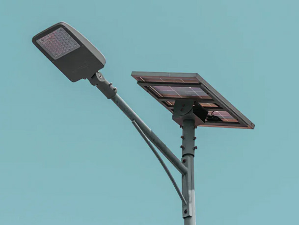
Integrated and Split Solar Street Lights Compariso
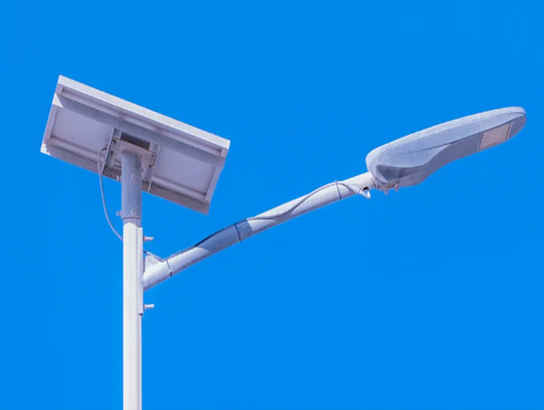
How to Choose the Right Solar Street Light Pole
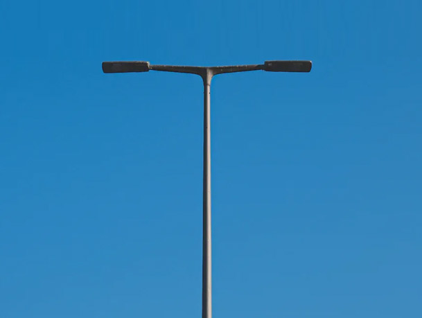
Street Light Pole Cost Factors and Quotation Compa
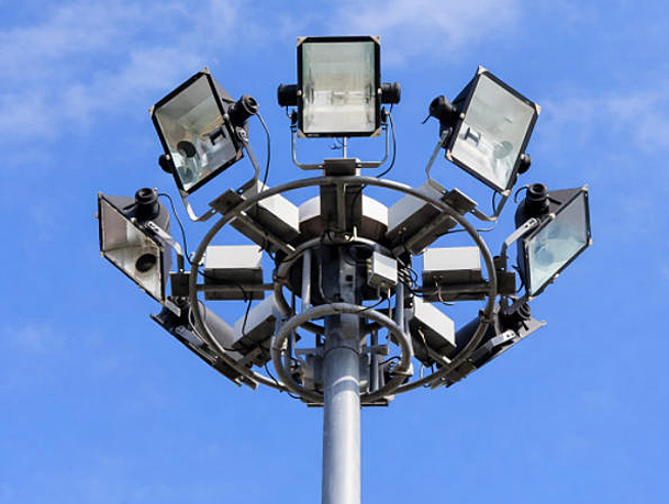
High Mast Light Specifications and Selection Guide
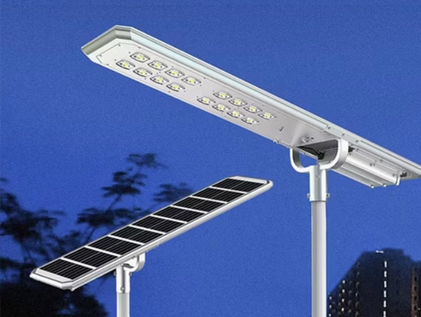
Features of All in One Solar Street Lights
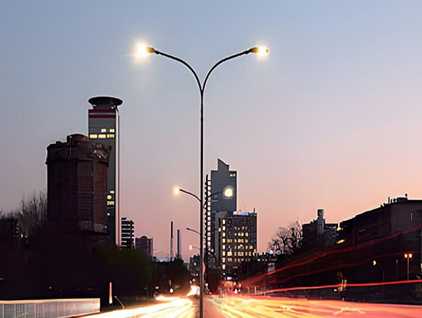
How to Choose the Right LED Street Lights for Your
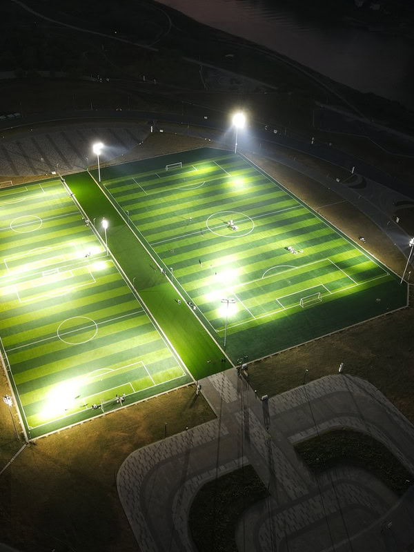
Select the Right LED Stadium Light for Football Pi
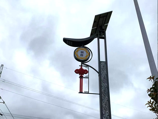
6-meter steel lamp post, 150W solar landscape ligh
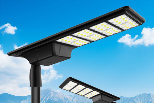
Solar Street Lights Installed at Baybay Black Sand
Contact Us
Get a custom lighting solution and quotation for your project. Outdoor lighting manufacturer in Yangzhou, ChinaAbout Jieyao LightingYangzhou Jieyao Lighting Equipment Co., Ltd. is an outdoor lighting manufacturer focused on solar street light systems and high mas... Do you have any questions or requests?
Email: jay@jieyaolighting.com

Click to Chat.
Im online now.
Hey, I'm Xu Jie from Jieyao Lighting. What can I do for you? Welcome to contact me, WhatsApp: +86 13815843784
WhatsApp Us
🟢 Online | Privacy policy