


Control receiving, storage, foundations, lifting, alignment, electrical interfaces, night commissioning and final records for galvanized steel roadway poles.
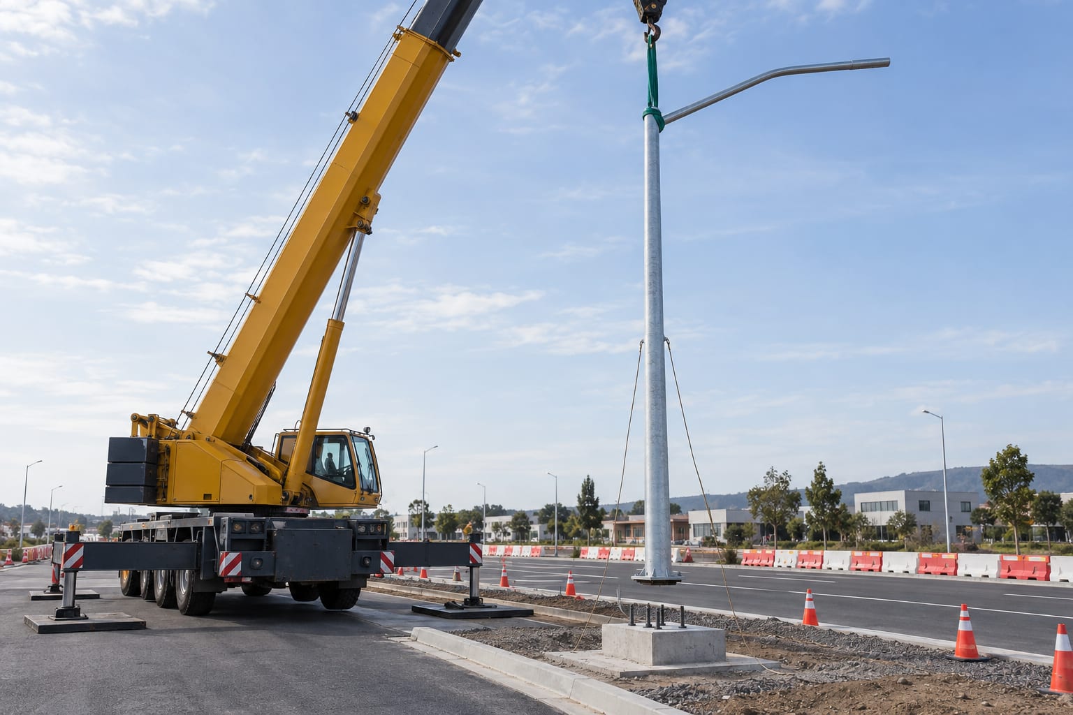
A street light pole installation checklist should control more than the moment when a crane raises the shaft. Quality can be lost during unloading, storage, ground assembly, anchor preparation, orientation, electrical connection or final adjustment. Each activity should use the approved pole mark and drawing so a correct component does not reach the wrong foundation.
This guide addresses galvanized steel roadway poles with flanged bases and common single- or double-arm arrangements. It does not replace the contractor's lift plan, traffic-management plan, electrical safety procedure, manufacturer instructions, responsible engineer's design or local legal requirements. Solar panels, batteries and controllers are covered by the existing solar street light installation FAQ rather than this structural pole guide.
Before mobilization, assemble the issued site plan, pole schedule, shop drawings, base and anchor details, foundation release, luminaire schedule, wiring diagram, lift plan, inspection forms and traffic arrangements. Check revision status and identify who may accept deviations. A drawing that was superseded during fabrication should not remain in the erection folder.
Confirm the definition of mounting height, arm direction, access-door orientation and pole location reference. Match pole types to station, coordinate or asset number. The street light pole shop drawing checklist helps close geometry and interface questions before components are released to site.
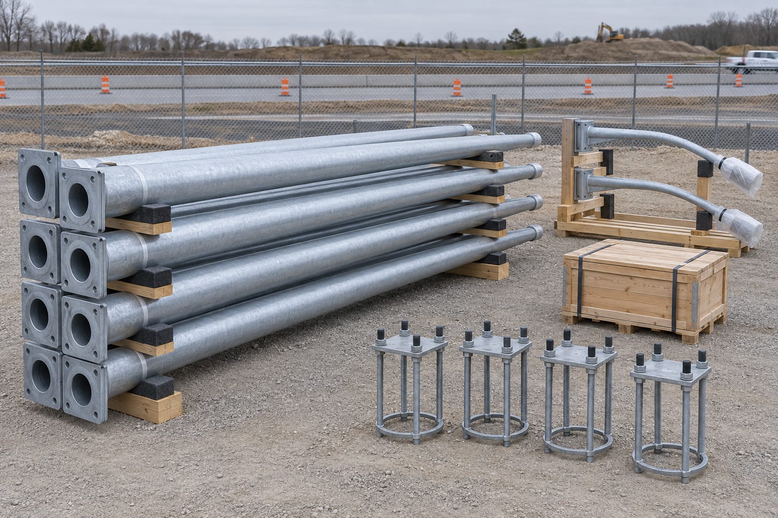
Compare bundles, crates and loose parts with the packing list. Record pole marks, shaft sections, arms, doors, luminaires where included, anchor assemblies, templates, nuts, washers and special hardware. Photograph package condition before restraints are removed. Missing or mixed accessories are easier to resolve while delivery identification remains visible.
Look for transport damage, abnormal bending, denting, open seams, flange impact, damaged threads, coating abrasion and water trapped in packaging. Do not assume that every surface mark is harmless or that every visual defect requires rejection. Record the location and obtain the specified assessment or repair decision before the area becomes hidden.
Use suitable lifting equipment, protected contact points and the planned unloading sequence. Do not drag finished shafts across the vehicle bed or ground. Bare chains, sharp forks and uncontrolled steel straps can damage zinc or deform thinner sections. Keep personnel outside the fall and roll zones defined by the site method.
Store poles on stable, aligned and padded supports above soil and standing water. Support long shafts at enough points to prevent local bending. Restrain round components from rolling and separate layers so one pole does not rub against another. Keep arms, doors and hardware linked to their pole marks and protect anchor threads from impact and contamination.
| Hold point | Evidence to check | Stop condition | Record |
|---|---|---|---|
| Delivery acceptance | Packing list, pole marks, visible condition and accessory count | Missing identity, significant damage or unmatched parts | Receiving report and photographs |
| Foundation release | Concrete release, level, bolt pattern, projection, conduit and orientation | Pattern mismatch, blocked conduit or unaccepted concrete | Survey and foundation checklist |
| Lift readiness | Crane setup, rigging, weather, exclusion zone and assembly condition | Unapproved lift path, unsuitable ground or uncontrolled traffic | Lift permit or pre-lift briefing |
| Mechanical completion | Plumb, orientation, base support, anchors, doors and finish | Unresolved alignment, support or connection issue | Pole-marked inspection sheet |
| Energization and handover | Earthing, circuits, controls, aiming, night test and punch closure | Unsafe electrical condition or incomplete required test | Commissioning and as-built package |
Confirm that the foundation has reached the release condition defined by the project specification or responsible engineer. Check finished elevation, pedestal condition, anchor position, bolt projection, thread condition, conduit location, working space and the orientation reference. A visually hard concrete surface is not evidence of accepted strength or completion.
Compare the actual bolt pattern with the current pole base drawing. Measure centers and diagonals using the agreed tolerance method. Confirm that nuts and washers match the approved anchor system and that the central cable route remains clear. The foundation and anchor bolt guide explains the civil interface from reaction input through pre-pour records.
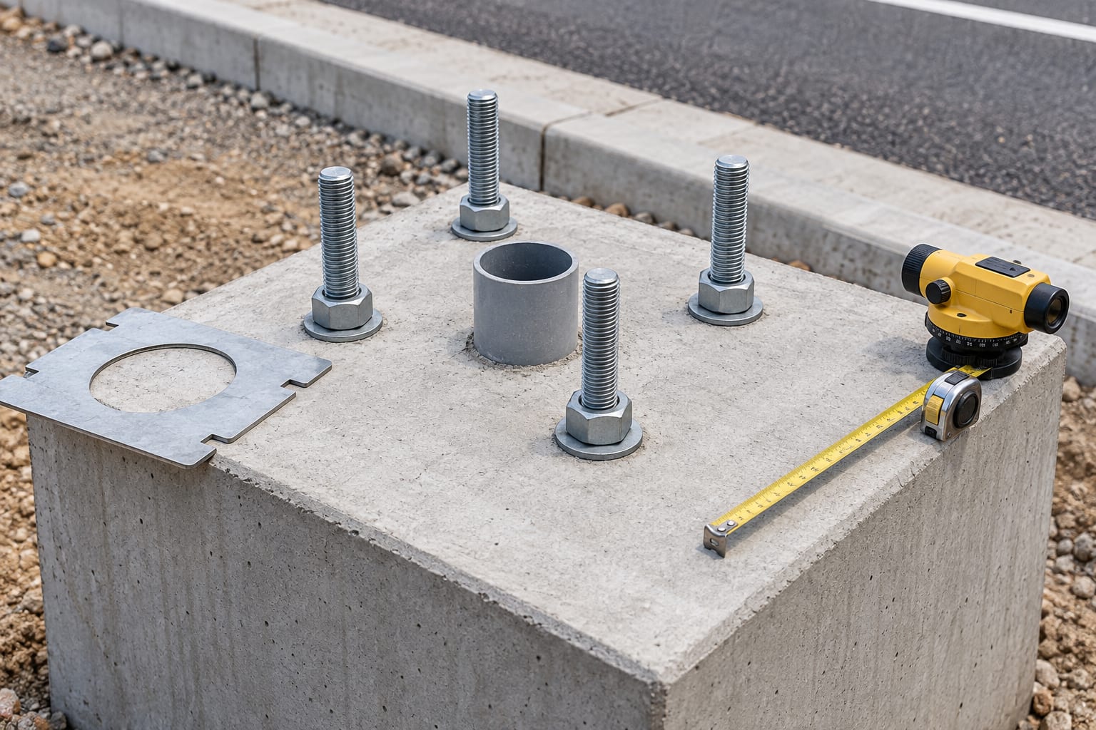
If the pole does not seat naturally over the anchors, stop and identify the cause. Field enlargement of holes, bending anchors, heating components or pulling the base into position with the nuts can damage the connection and invalidate the reviewed detail. A rotated cage can also allow the plate to fit while placing the door or arm in the wrong direction.
Record measured dimensions and compare them with both the base-plate and civil drawings. The responsible parties should approve any correction. Keep replacement hardware traceable by material, grade and finish. A fast site workaround can become a concealed long-term defect once grout, covers or paving hide the base.
Roadside and median installation exposes crews, road users and equipment to moving traffic. Implement the approved traffic-management plan before crane setup or component movement. Define lane closures, barriers, approach signs, safe pedestrian routes, delivery access and an exclusion zone for the pole swing path.
Keep the public and nonessential personnel outside lifting and electrical areas. Review emergency access and the effect of construction vehicles on sight lines. Lighting work should not create an uncontrolled dark or obstructed route for adjacent traffic. Conditions can change by time of day, so the work window should match the approved plan.
Select lifting equipment using the actual pole assembly mass, radius, hook height, boom configuration and site restrictions. The competent lifting team verifies crane capacity and the ground or pavement support beneath outriggers. Underground utilities, trenches, soft shoulders and recently backfilled foundations can limit suitable setup positions.
Establish level support and use the required mats or load-spreading system. Confirm overhead cables, trees, signs and nearby structures along the boom and load path. Weather limits, including wind, follow the approved lift plan and equipment requirements rather than a generic value copied from another project.
Place the shaft on stable padded supports before fitting arms, luminaires or internal cables. Check the pole mark and drawing again. Inspect spigots, flange faces, slip joints, access openings and fasteners for damage or contamination. Components should seat without forcing, uncontrolled hammering or unapproved modification.
Whether arms and luminaires are installed at ground level depends on the lift method, component design, mass, wind, transport condition and site plan. Ground assembly can reduce elevated work, but it changes the lifted center of gravity and risks fixture damage if the rigging is not designed for the complete assembly.
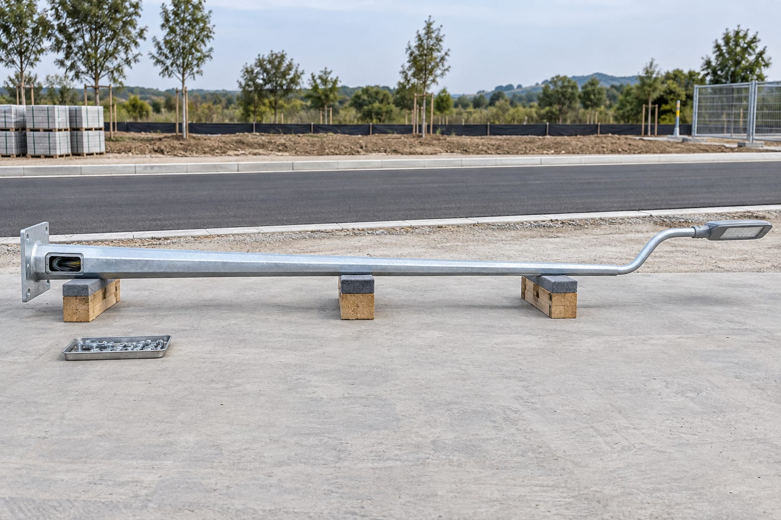
Use the specified cable type and protect it from sharp edges at the base opening, access door, shaft joints and arm connection. Pulling force, bend radius and lubricant follow the cable and project requirements. Avoid leaving connectors, splices or excess cable where they can be crushed during assembly or contact retained water.
Keep the incoming circuit, luminaire lead, earthing conductor and any control cable identifiable. Verify that the door opening remains usable after termination equipment is installed. If a pull becomes unusually difficult, stop and check the route rather than increasing force until the cable jacket is damaged inside the shaft.
The lift plan should define sling type, contact protection, attachment position, load control and removal method. Do not improvise a lift from the luminaire arm, access opening or another feature not approved for rigging. Slings and edge protection should control the shaft without crushing, slipping or cutting the finish.
Tag lines may help control rotation when they are part of the safe method. The team should remain outside the suspended-load zone and maintain clear communication with the operator. Recheck the balance after any change to the arm, luminaire or cable assembly, because added top equipment can move the center of gravity.
Protect anchor threads and conduit while lowering the pole. The base plate should approach squarely and remain controlled; repeated contact can damage threads, displace leveling hardware or cut cables. Workers should not place hands beneath the plate or between the shaft and fixed objects.
Feed cables through the intended opening without trapping them. Confirm pole type and orientation before the plate is fully seated. If the pole binds on an anchor, lift clear and inspect rather than using the crane or nuts to force the connection.
Use the site plan, road centerline, north arrow or another defined reference to orient the pole. A symmetrical bolt pattern can permit several positions even when only one gives the correct arm and door direction. Median double-arm poles, mirrored roadside types and junction poles need particularly clear marks.
The access door should face the approved maintenance side and remain clear of barriers, planting and traffic where practical. Check luminaire orientation and tilt against the lighting layout, not only the arm appearance. Mark the final direction before the lifting equipment releases full control.
Projects may use direct bearing, designed leveling nuts, approved shims or a specified grout system. Each detail creates a different load path, drainage condition and installation sequence. Use the arrangement shown on the current drawing; do not combine methods or build an uncontrolled stack of washers to correct level.
Confirm that the base has the intended bearing and that required drainage or grout access remains open. Excessive unsupported space beneath the plate can concentrate load and trap water. Any correction to foundation level, base geometry or support method needs the defined review before the lift is closed.
Measure verticality using the project method and a suitable reference on the shaft. Polygon faces, taper and local coating texture can affect readings, so the inspection method should be consistent. Take measurements in more than one direction and at a time when wind or suspended rigging does not distort the result.
Adjust only through the approved base arrangement. Recheck orientation, base support and anchor engagement after correction. A pole can be plumb but aimed incorrectly, or correctly oriented with uneven support. Mechanical completion requires all of these conditions to agree.
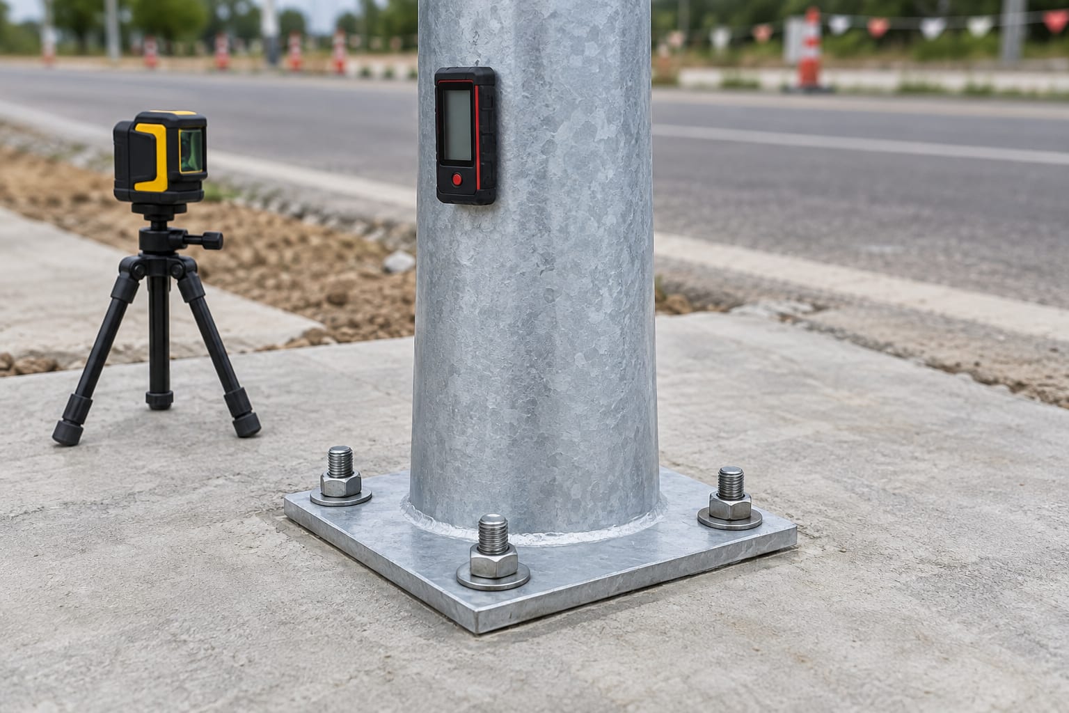
Verify nut, washer, thread and coating condition before final connection. Tightening method, sequence, tools, lubrication assumptions and any recheck requirement depend on the approved design and specification. One universal torque value should not be applied to unknown anchor grades, finishes or connection concepts.
Record the procedure and result where required. Maintain usable thread engagement and do not damage protective finishes with unsuitable tools. If threads are galled, contaminated or mechanically damaged, obtain an accepted remedy rather than substituting unrelated nuts or reducing engagement.
Where grout is specified, prepare surfaces and place the approved material to achieve the intended bearing without voids or blocked drainage. Curing and release follow the product and project requirements. Do not conceal the base before alignment, hardware and support inspections are complete.
Keep water from ponding around the pedestal or entering the shaft. Covers, skirts or sealants should match the approved detail and should not create a hidden water trap. Finished paving, soil and mulch levels must leave the base inspectable and the access opening usable.
Confirm spigot diameter, insertion, fastener arrangement, rotation control and luminaire tilt. A fixture that appears to fit may still have inadequate engagement or a different mounting interface. Use the required fasteners and locking method, and protect cables from pinch points at the arm or tenon.
For a 10m single-arm pole, verify the road-side orientation. For a 10m double-arm pole, confirm both fixtures and any left/right differences. Shorter 6m and 8m galvanized poles still need the same identity and interface discipline even when lifting is simpler.
Install terminal equipment, protective devices and cable supports according to the electrical design. Maintain separation, bend space and safe access. Glands, grommets or edge protection should prevent abrasion and water paths. Loose conductors should not carry mechanical load or obstruct the door.
Check the door, hinges or retaining system, gasket, lock and reinforcement. The cover should close without trapping cables and remain secure against weather and unauthorized access. Keep pole identity visible without placing labels where they damage the coating or expose sensitive project information.
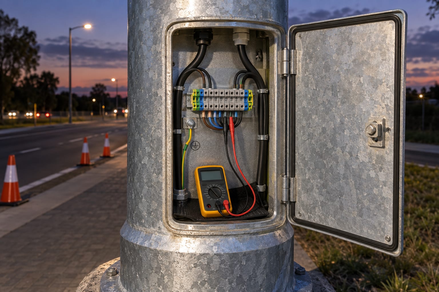
Electrical work should be completed and tested by qualified personnel under the project's isolation and energization procedure. Confirm the physical earthing or bonding provision, conductor routing, circuit identity, protective devices and terminations. The pole drawing coordinates attachment points; the electrical designer and contractor control the full system.
Perform the required continuity, insulation, polarity, protection and functional checks using applicable standards and approved forms. Do not energize an open or wet compartment or a circuit with unresolved damage. Record results by pole or circuit so a failure can be located and corrected without repeating the entire route.
Examine galvanized and coated surfaces after unloading, assembly and erection. Pay attention to sling contact, flange edges, door frames, arm joints, fastener areas and base work. Clean contamination and assess damaged areas against the specified coating standard and project acceptance criteria.
Use only the approved repair method and document significant locations. Uncontrolled grinding or ordinary decorative paint may remove zinc or create an incompatible patch. The article What Is a Galvanized Street Light Pole? explains how fabrication, handling, drainage and exposure affect the protection system.
Inspect the route in daylight after cranes and temporary supports are removed. Confirm pole marks, coordinates, plumb, arm direction, fixture orientation, door security, base condition, coating repair, clearances and maintenance access. Repeated pole lines make inconsistent height, tilt or arm direction easier to see from a long viewpoint.
Check that landscaping, barriers, paving and signs do not block the access opening or conflict with the luminaire. Verify that covers and work areas are clean and that temporary restraints, packaging and exposed materials have been removed. Record punch items with a pole mark and close-up plus context photographs.
Night commissioning confirms more than switch-on. Check that each luminaire belongs to the correct circuit and control group, reaches the intended output scene and aims in the approved direction. Walk or drive the route as permitted to observe dark transitions, glare, inconsistent color, failed units and unexpected spill.
Where the contract requires photometric verification, use the agreed grid, equipment and maintained or initial basis. Record weather and operating scene. Test normal, reduced, override and failure modes as applicable. Any aiming or control change should be marked in the final schedule so maintenance teams can restore the accepted arrangement.

A useful punch list identifies the asset, exact issue, responsible party, due stage and acceptance evidence. Avoid descriptions such as “several poles need adjustment” without locations. Separate safety-critical or energization-blocking items from appearance, documentation and minor completion work.
Reinspect corrected work and retain before-and-after evidence where required. If a correction changes arm orientation, aiming, hardware, coating or drawing information, update the relevant record. Verbal closure can leave future teams uncertain about whether a condition was accepted or overlooked.
The final package should connect as-built pole locations with drawings, schedules, foundation records, mechanical inspections, coating repairs, electrical tests, control settings, night commissioning and closed punch items. Include operation and maintenance information for the supplied equipment. Organize records so one pole mark can be followed across disciplines.
Handover should also identify approved spare doors, drivers, luminaires, hardware or repair materials where included. Record warranty and contact information only as defined by the contract. A collection of unrelated photographs is not a complete asset record; dates, revisions and physical locations make evidence useful.
| Record group | Minimum linkage | Why it matters after handover |
|---|---|---|
| As-built geometry | Pole mark, coordinate, type, arm direction, luminaire and drawing revision | Supports replacement, road changes and orientation checks |
| Civil and base | Foundation release, anchor survey, support detail and final base inspection | Explains the concealed support and future repair boundary |
| Mechanical and coating | Verticality, connections, finish observations and approved repairs | Creates a baseline for later condition inspection |
| Electrical and controls | Circuit, protection, earthing, control address and required test results | Speeds fault isolation and preserves the operating strategy |
| Commissioning and closeout | Night scene, aiming changes, punch closure, spares and maintenance data | Defines the accepted installation condition |
Repeated failures include using an obsolete drawing, mixing pole marks, storing shafts directly on soil, damaging threads during lowering, rotating the door toward traffic, forcing a mismatched bolt pattern, improvised washer stacks, trapped cables, unrecorded coating damage and commissioning only by daytime switch test.
Most are coordination failures rather than complex manufacturing problems. Hold points, clear responsibility and asset-linked records make them visible while correction is still practical. A street light pole installation checklist should match the project risk and contract; adding forms that nobody reviews does not improve the installation.
The pole supplier commonly provides the approved shaft, arm, base interface, anchor components where included, manufacturing documents, packing information and agreed installation guidance. The site contractor controls unloading, storage, temporary works, lifting, traffic management, erection, electrical work and field records within its contract.
Project designers and supervisors review civil, structural, lighting and electrical requirements. Exact boundaries vary, so state them before delivery. For taller or segmented configurations such as a 12m highway street light pole, transport, joint assembly and crane planning deserve additional detail.
After the foundation reaches the specified release condition and all readiness checks pass.
Only if the approved lift plan and manufacturer information specifically allow it.
It depends on the assembly design, lifting balance, site access and approved method.
Stop work, measure the interface and obtain an approved correction; do not force it.
No. Use the project procedure for the actual anchor grade, finish and connection.
Use the defined project method in at least two directions on a suitable shaft reference.
Qualified personnel follow the approved electrical and energization procedure.
No. Check circuits, controls, aiming, visual continuity and required night criteria.
Assess it against the specified standard and use the approved compatible method.
As-builts, base checks, inspections, tests, controls, night results and punch closure.
Send the pole schedule, approved luminaire data, wind basis, base and anchor interface, coating requirement, delivery limits and document list. Jieyao can coordinate the galvanized shaft, arm, anchor and manufacturing information for the project installation team.
Discuss Your Installation Package
Street Light Pole Height Guide: How to Select Moun
Integrated and Split Solar Street Lights Compariso
How to Choose the Right Solar Street Light Pole
Street Light Pole Cost Factors and Quotation Compa
High Mast Light Specifications and Selection Guide
Features of All in One Solar Street Lights
How to Choose the Right LED Street Lights for Your
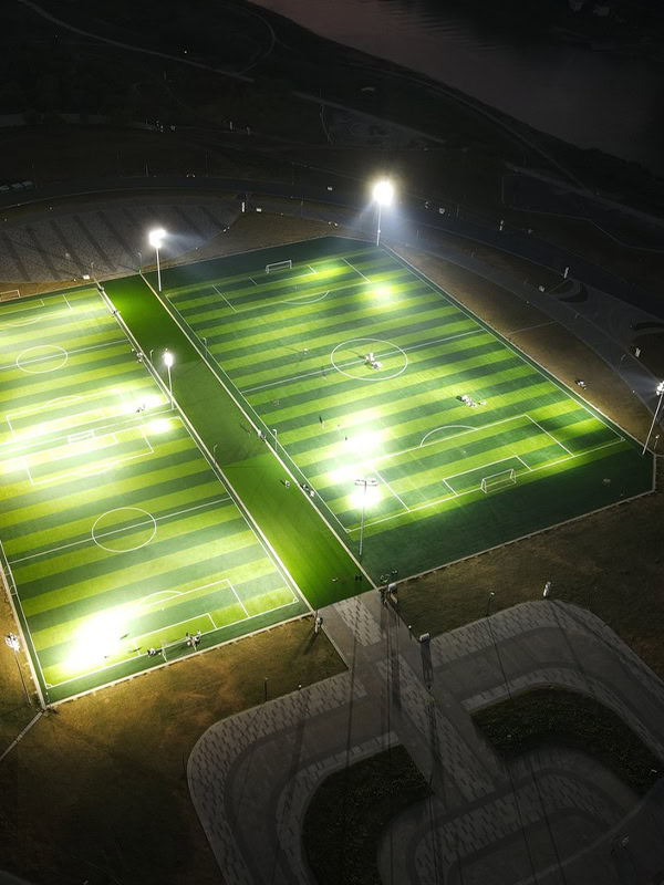
Select the Right LED Stadium Light for Football Pi
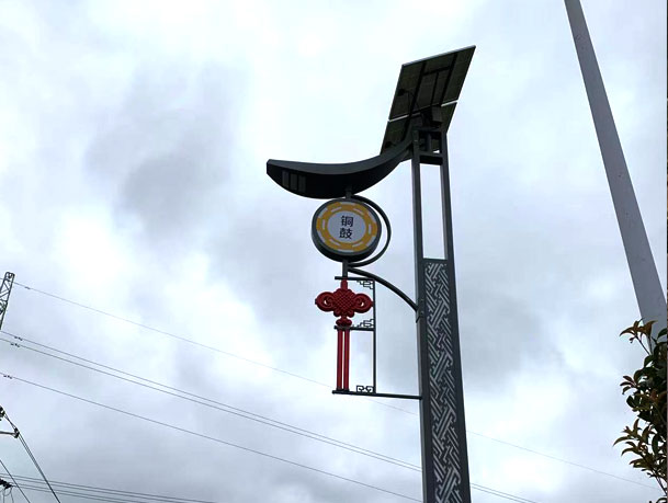
6-meter steel lamp post, 150W solar landscape ligh
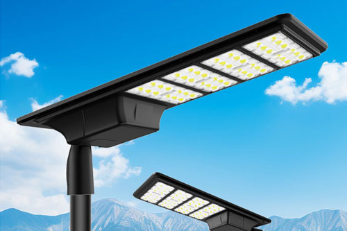
Solar Street Lights Installed at Baybay Black Sand
Contact Us
Get a custom lighting solution and quotation for your project. Outdoor lighting manufacturer in Yangzhou, ChinaAbout Jieyao LightingYangzhou Jieyao Lighting Equipment Co., Ltd. is an outdoor lighting manufacturer focused on solar street light systems and high mas... Do you have any questions or requests?
Email: jay@jieyaolighting.com

Click to Chat.
Im online now.
Hey, I'm Xu Jie from Jieyao Lighting. What can I do for you? Welcome to contact me, WhatsApp: +86 13815843784
WhatsApp Us
🟢 Online | Privacy policy