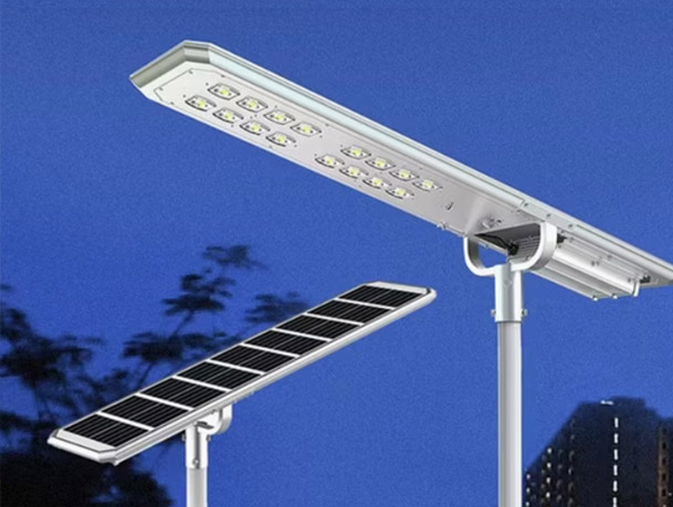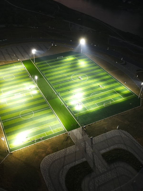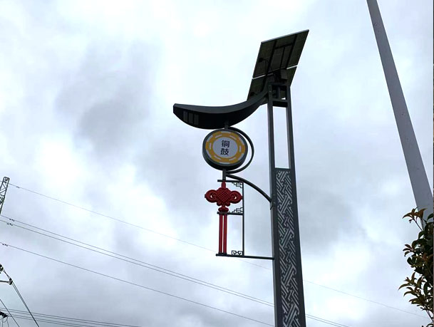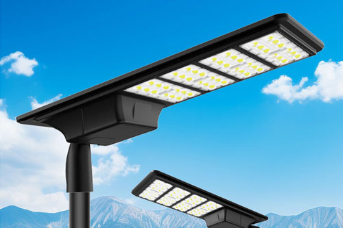
Nominal labels do not replace a checked arm-end and luminaire-socket fit.
Which dimensions and loads should be exchanged?
Send the actual luminaire make/model or its approved interface drawing. The pole-side schedule should state arm outreach, rise, orientation, connection type, spigot outside geometry and available insertion length. The luminaire schedule should state socket geometry, allowed tilt or aiming range, mass, projected area, center of gravity and any manufacturer fastening limits. Where a camera, sign or other device shares the pole, include its load and location rather than treating the luminaire as the only attachment.
The project structural designer determines the governing wind and strength checks. The buyer should not choose arm wall thickness from a catalog image. The street light pole product range shows the wider assembly context, while the shop-drawing checklist covers release documentation.
Table 1. Arm-to-luminaire interface schedule
| Interface | Buyer/manufacturer input | Fit or design check |
|---|
| Arm geometry | Outreach, rise, angle, orientation and connection drawing | Optical position, transport and structural load path |
| Luminaire socket | Approved socket drawing and insertion/fastening requirements | Engagement, aiming and accessible fastening |
| Equipment loads | Mass, area, center of gravity and future attachment allowance if specified | Arm, shaft and foundation reactions |
| Cable route | Entry points, conductor envelope and protection requirements | Continuous protected path to the luminaire |
Select the arm arrangement for the lighting layout
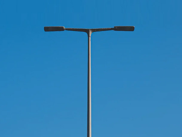
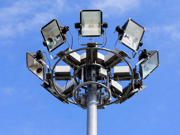
Single-arm, double-arm and multi-head arrangements are different structural and photometric configurations. The lighting designer defines target positions and aiming; the pole designer coordinates the resulting arm geometry and loads. A double-arm assembly should show each outreach and azimuth, not merely say “two arms.” Confirm whether arms are factory-welded, bolted or fitted to an approved head, and keep the connection detail aligned with galvanizing, transport and erection requirements.
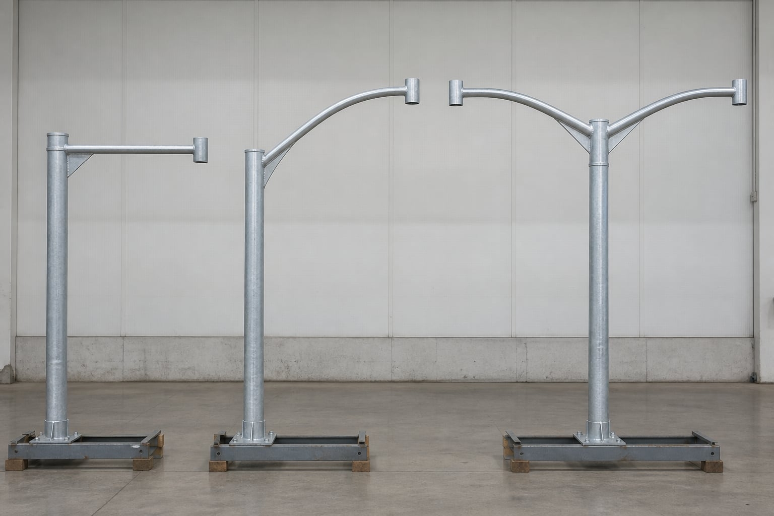
Different arm forms require their own type marks, load inputs and mounting details.
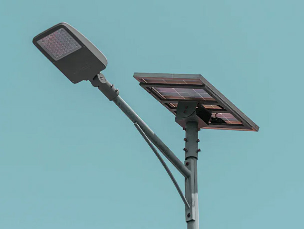
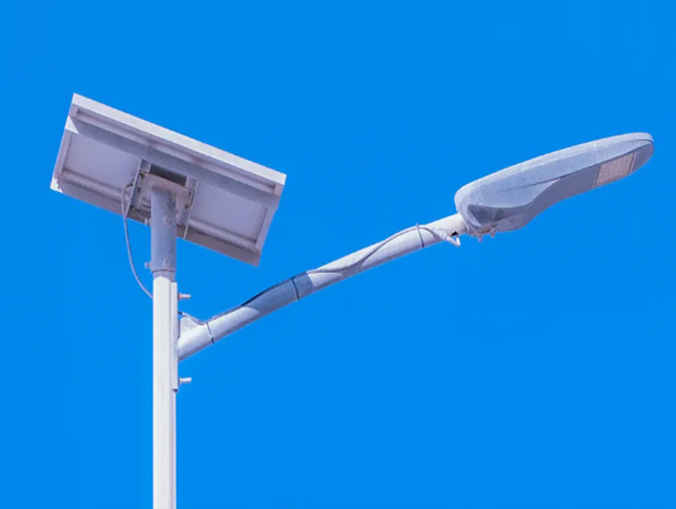
The double-arm street light pole and single-arm street light pole illustrate distinct product configurations. Neither name alone determines the correct outreach, wall schedule or wind basis for a new site.
Prove fit, fastening and cable protection before dispatch
Use approved sample components or controlled dimensions to verify spigot/socket engagement and luminaire aiming. Check that bolts or set screws bear on the intended surface, remain accessible after aiming and are tightened under the luminaire manufacturer’s procedure. A mock-up should expose clashes or loose fit without forcing a connection. Any adapter must be identified in the scope and reviewed for loads, electrical continuity and corrosion compatibility.
Route conductors through the intended internal path with protection at entry and exit points. Keep sharp edges, blocked passages and unreviewed holes out of the installation plan. The access door and terminal compartment must accommodate the actual cable arrangement shown on the approved electrical interface drawing.
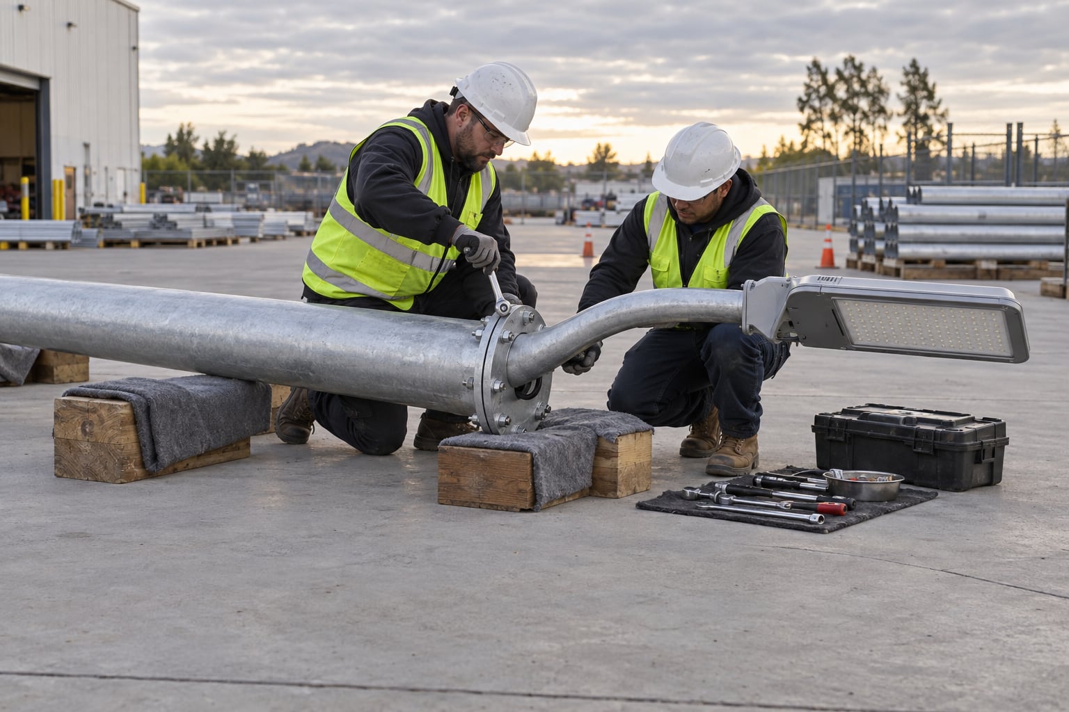
A supported preassembly can reveal connection or aiming problems before the pole is lifted.
Record drawing and inspection hold points
The released general arrangement should identify each arm and luminaire type, connection section, orientation, fixing details, internal cable path and equipment weights. Inspection records should confirm fabricated geometry, finish, fit-up, complete fasteners and protected packing. Site acceptance then checks erected orientation and aiming under the project lighting design, with electrical tests performed by the responsible contractor. The installation and erection checklist covers the wider handover sequence.
Table 2. Release and handover evidence
| Stage | Record | Question before release |
|---|
| Design | Arm and luminaire interface drawings, loads and type schedule | Are all supplier inputs on the same revision? |
| Fit-up | Measured geometry or approved sample trial, fastening plan | Does the actual luminaire mount securely and aim correctly? |
| Factory dispatch | Inspection, finish and component/packing list | Are arms, adapters and fasteners traceable by type? |
| Site | Erected orientation, aiming and electrical completion evidence | Does the installed layout match the approved plan? |
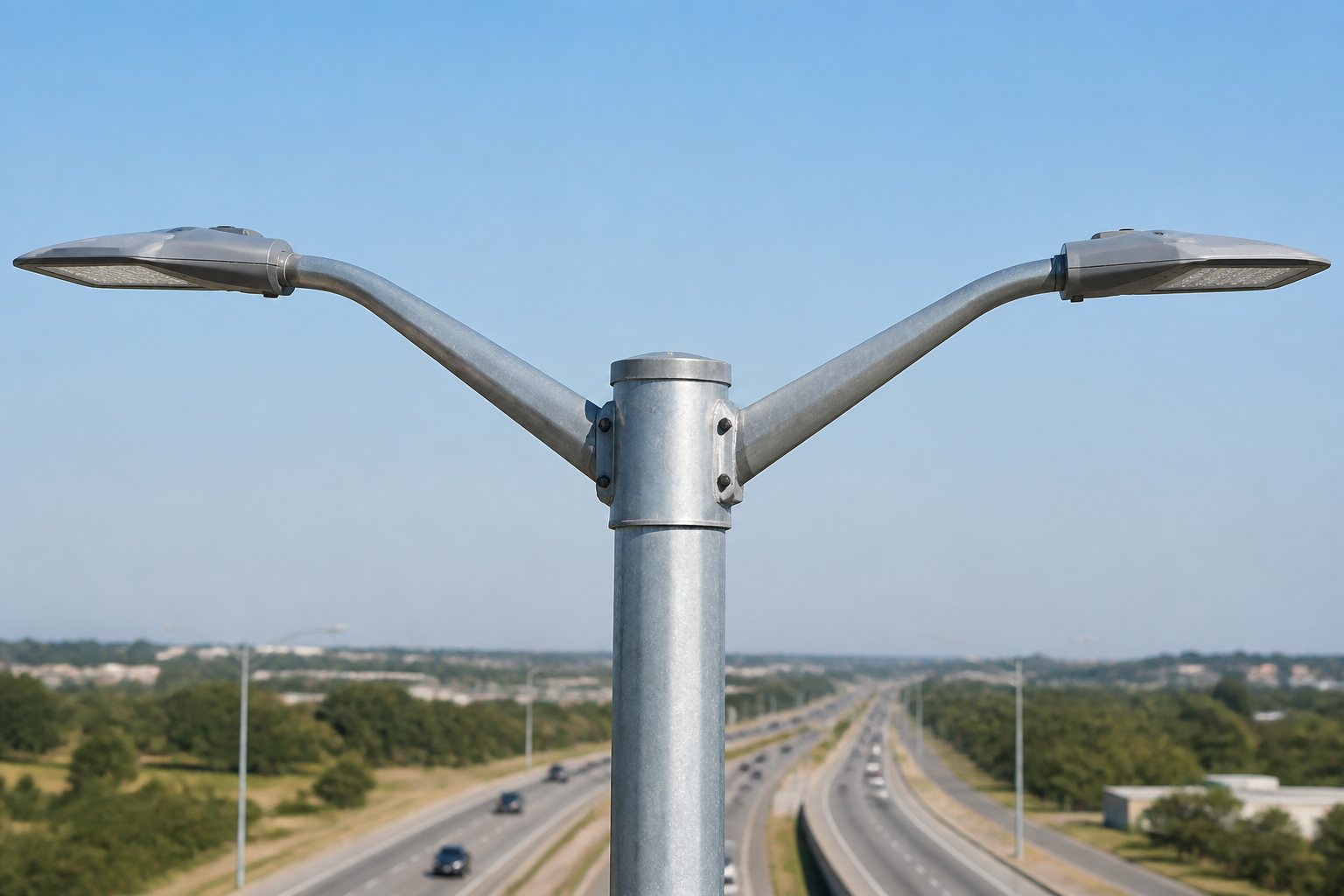
The finished arm arrangement should match the approved azimuth and luminaire interface.
Frequently asked questions
Is a nominal spigot size enough to approve fit?
No. Check the actual mating drawings, engagement, tolerances, fastening and aiming range.
Can the luminaire be changed after pole fabrication?
Only after reviewing the new socket, load, projected area, aiming and electrical interface against the approved pole design.
Do single and double arms use the same structural check?
No. Their geometry and load distribution differ; the project designer must check the actual configuration.
Should luminaires be fitted before erection?
A controlled trial fit can catch mismatches. The final erection sequence depends on lifting, transport and project installation procedures.
What should an RFQ include?
Send luminaire and arm drawings, load data, orientation schedule, connection method, cable route, finish and inspection requirements.
For a matching arm and luminaire scope review, send the approved equipment and pole drawings.