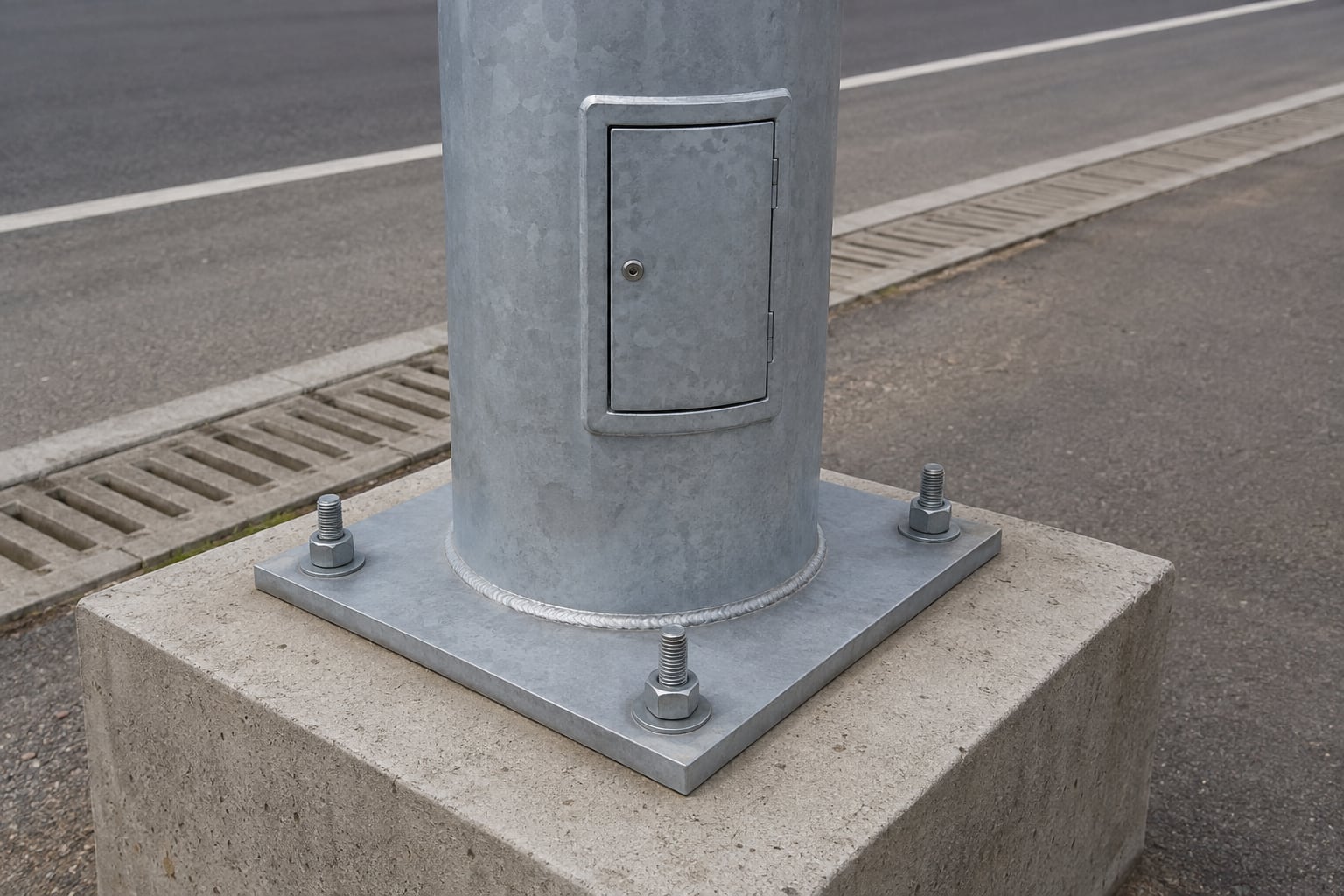
Door location must be usable after the pole is installed, not only while the shaft is in the factory.
What should an access-door specification define?
Specify the opening position and orientation, usable clear opening, door retention and locking method, required internal equipment envelope, cable entry/exit path, protection of conductors at edges, bonding/earthing interface where required, and the accepted finish around the frame. The project electrical designer must approve conductor sizing, terminals, protection and separation; the pole fabricator needs those interfaces early enough to design the shaft and reinforcement.
Do not copy a fixed handhole height or dimension from an unrelated pole. Available internal space depends on shaft diameter and taper, base plate or direct-burial design, door frame, stiffeners and the equipment specified for the project. Use the steel pole range for product context and the shop-drawing checklist for the wider approval package.
Coordinate door location with maintenance and structure
The door should face a safe and reachable maintenance position consistent with the site plan. Check guardrails, medians, walls, planting, parked vehicles, splash zones and the direction in which the cover opens or is removed. Show the door orientation on the general arrangement rather than leaving it to the erection crew. If poles of one type need different orientations, give those variants explicit type marks.
The opening interrupts the shaft wall and may need a designed frame or local reinforcement. Its position relative to base welds, gussets, slip joints and lifting points matters. Structural adequacy belongs to the approved pole design; do not cut or enlarge an opening on site because a terminal block does not fit.
Table 1. Access-door and cable-route drawing checks
| Interface | Show on drawing | Confirm with |
|---|
| Door and frame | Orientation, clear opening, closure, frame and local reinforcement | Pole structural designer and maintenance owner |
| Internal equipment | Mounting envelope, removal space, terminal location | Electrical designer and equipment supplier |
| Cable route | Conduit entry, bend space, edge protection, path to arm/luminaire | Civil/electrical teams and fabricator |
| Site access | Roadside/footway orientation and working clearance | Installer and asset maintainer |
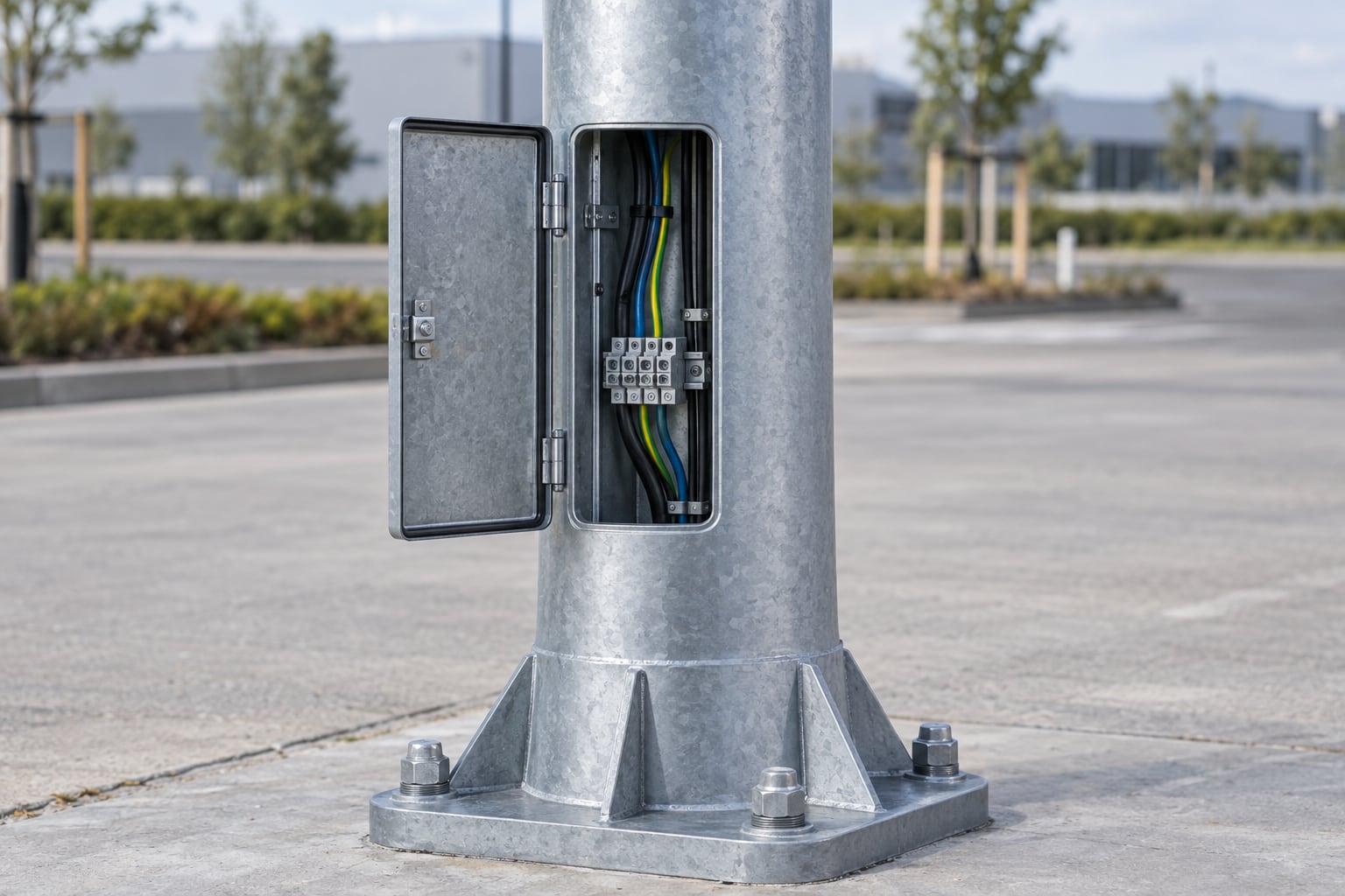
Check that the terminal area and cable route remain accessible without conductor abrasion or obstruction.
Protect cable entry and keep the service compartment workable
The civil conduit position, base opening and internal pathway must line up. Cable bend radius, pull space and any separation between circuits are project electrical-design inputs, not values to assume from a pole photograph. Sharp edges, exposed welds, loose hardware and trapped water can damage conductors. Specify bushings or other edge protection where the design requires them, and keep the termination area clear of internal stiffeners or anchor hardware.
A removable door should close against the intended seal or fit after terminals are installed. The fastening method should allow authorized inspection while preventing unintended opening. Confirm whether equipment, terminals, protective devices and wiring are supplied with the pole or by another contractor; this is a frequent quotation gap.
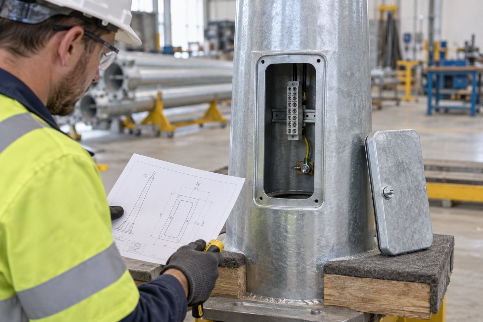
Drawing review should verify the opening, electrical envelope and door fit before fabrication release.
Inspect the assembly before shipment and at site
Factory checks should confirm the approved opening size and position, frame and weld condition, door fit, hardware, finish continuity and the agreed internal mounting features. The electrical contractor should separately verify its own conductors, terminations and protective equipment under the project test plan. After delivery, inspect for a bent door, missing fasteners, blocked opening, damaged coating or shipping debris before erection.
At site, verify door orientation and safe access before final tightening and electrical completion. The installation and erection checklist covers the broader foundation-to-handover sequence.
Table 2. Hold points and evidence for an RFQ or inspection plan
| Stage | Evidence | Release question |
|---|
| Design | Type drawing, orientation schedule, electrical equipment envelope | Can equipment be installed and serviced safely? |
| Fabrication | Opening/frame dimensions, weld and fit inspection | Does the built opening match the released design? |
| Finish/packing | Coating and protected-door condition record | Will the door and coating arrive usable? |
| Site handover | Door orientation, access and electrical completion records | Can the owner maintain the finished asset? |
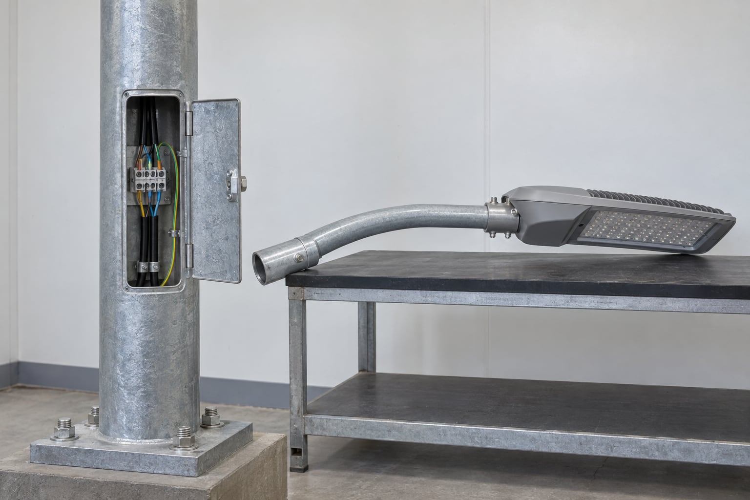
Service access, internal wiring and the arm/luminaire path should agree across the pole package.
Frequently asked questions
Does every street light pole need the same door size?
No. The opening and reinforcement follow the pole section, equipment envelope and project access requirements.
Can the access door face the road?
Only if the site’s maintenance and safety plan permits it. Orient the door on the approved layout before erection.
Are terminals and wiring included with the pole?
Not automatically. The quotation should list equipment and electrical-scope inclusions separately.
Can an opening be enlarged after galvanizing?
Do not treat that as a routine site adjustment. It requires structural, finish and electrical review under the project change process.
What should the buyer send with an RFQ?
Send the pole type, site orientation, electrical equipment envelope, cable/conduit interface, required door hardware and inspection evidence.
For a project-specific access-door and routing review, send the pole and electrical interface drawings.